TPS65163
www.ti.com
SLVSA28 –OCTOBER 2009
VIN
VS
CIN
COUTB
COUTA
R1
CFF
SW
GD
FB
R2
COMP
SS
CSS
CCOMP
RCOMP
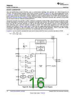
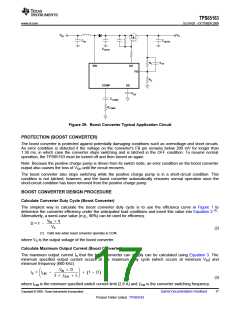
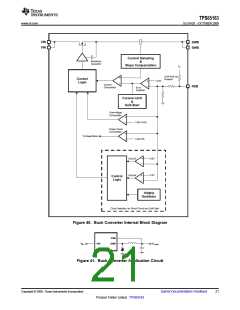
Figure 39. Boost Converter Typical Application Circuit
PROTECTION (BOOST CONVERTER)
The boost converter is protected against potentially damaging conditions such as overvoltage and short circuits.
An error condition is detected if the voltage on the converter's FB pin remains below 200 mV for longer than
1.36 ms, in which case the converter stops switching and is latched in the OFF condition. To resume normal
operation, the TPS65163 must be turned off and then turned on again.
Note: Because the positive charge pump is driven from its switch node, an error condition on the boost converter
output also causes the loss of VGH until the circuit recovers.
The boost converter also stops switching while the positive charge pump is in a short-circuit condition. This
condition is not latched, however, and the boost converter automatically resumes normal operation once the
short-circuit condition has been removed from the positive charge pump.
BOOST CONVERTER DESIGN PROCEDURE
Calculate Converter Duty Cycle (Boost Converter)
The simplest way to calculate the boost converter duty cycle is to use the efficiency curve in Figure 1 to
(1)
determine the converter efficiency under the anticipated load conditions and insert this value into Equation 2
Alternatively, a worst-case value (e.g., 90%) can be used for efficiency.
.
V
´ η
IN
D = 1 -
VS
(2)
(1) Valid only when boost converter operates in CCM.
where VS is the output voltage of the boost converter.
Calculate Maximum Output Current (Boost Converter)
The maximum output current IS that the boost converter can supply can be calculated using Equation 3. The
minimum specified output current occurs at the maximum duty cycle (which occurs at minimum VIN) and
minimum frequency (600 kHz).
æ
V
´ D
ö
÷
ø
IN
IS
=
I
-
´ 1 - D
(
)
ç LIM
è
2 ´ ¦SW ´ L
(3)
17
where ILIM is the minimum specified switch current limit (2.8 A) and ƒSW is the converter switching frequency.
Copyright © 2009, Texas Instruments Incorporated
Submit Documentation Feedback
Product Folder Link(s) :TPS65163

 TI [ TEXAS INSTRUMENTS ]