TPS54560
www.ti.com
SLVSBN0 –MARCH 2013
DETAILED DESCRIPTION (continued)
VIN
TPS54560
VIN
i1 ihys
R
R
UVLO1
UVLO1
10 kW
EN
EN
Node
5.8 V
VEN
R
R
UVLO2
UVLO2
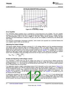
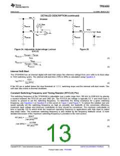
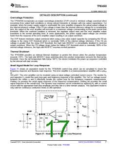
Figure 24. Adjustable Undervoltage Lockout
(UVLO)
Figure 25.
V
- V
STOP
START
R
=
UVLO1
I
HYS
(2)
(3)
V
ENA
R
=
UVLO2
V
- V
ENA
START
+ I
1
R
UVLO1
Internal Soft-Start
The TPS54560 has an internal digital soft-start that ramps the reference voltage from zero volts to its final value
in 1024 switching cycles. The internal soft-start time (10% to 90%) is calculated using Equation 4
1024
t
(ms) =
SS
f
(kHz)
SW
(4)
If the EN pin is pulled below the stop threshold of 1.2 V, switching stops and the internal soft-start resets. The
soft-start also resets in thermal shutdown.
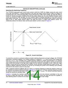
Constant Switching Frequency and Timing Resistor (RT/CLK) Pin)
The switching frequency of the TPS54560 is adjustable over a wide range from 100 kHz to 2500 kHz by placing
a resistor between the RT/CLK pin and GND pin. The RT/CLK pin voltage is typically 0.5 V and must have a
resistor to ground to set the switching frequency. To determine the timing resistance for a given switching
frequency, use Equation 5 or Equation 6 or the curves in Figure 5 and Figure 6. To reduce the solution size one
would typically set the switching frequency as high as possible, but tradeoffs of the conversion efficiency,
maximum input voltage and minimum controllable on time should be considered. The minimum controllable on
time is typically 135 ns which limits the maximum operating frequency in applications with high input to output
step down ratios. The maximum switching frequency is also limited by the frequency foldback circuit. A more
detailed discussion of the maximum switching frequency is provided in the next section.
92417
f sw (kHz)0.991
RT (kW) =
(5)
101756
RT (kW)1.008
f sw (kHz) =
(6)
Copyright © 2013, Texas Instruments Incorporated
Submit Documentation Feedback
13
Product Folder Links: TPS54560

 TI [ TEXAS INSTRUMENTS ]