TPS43060
TPS43061
SLVSBP4A –DECEMBER 2012–REVISED DECEMBER 2012
www.ti.com
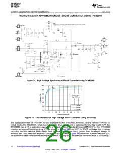
boost topology the maximum crossover frequency is typically limited by the right-half plane zero (RHPZ). The
RHPZ can be estimated with Equation 40. The compensation design should be done at the minimum input
voltage when the RHPZ is at the lowest frequency. The crossover frequency should also be limited to less than
1/5 of the switching frequency. Equation 41 and Equation 42 are used to calculate the maximum recommended
crossover frequency. For this example design, Adc = 11.3 V/V, ƒPmod = 1.93 kHz, ƒZmod = 1.45 MHz, ƒRHPZ = 57.9
kHz, ƒco1 = 14.5 kHz, and ƒco2 = 150 kHz. The target fco is 14.5 kHz.
VIN min
3
3
6V
V
Adc =
´
=
´
40 2´ RSENSE ´ IOUT 40 2´10mW ´ 2A
= 11.3
V
(37)
1
VOUT
IOUT
1
fPmod
=
=
=
=
= 1.93kHz
15V
2p´
´ 22mF
2p´
´ COUT
2A
(38)
(39)
1
1
fZ mod
=
2p´ ESR ´ COUT 2p´ 5mW ´ 22mF
= 1.45MHz
VOUT
15V
æ
ç
ö2
÷
ö2
IOUT
VIN
6V
æ
2A
2p´ 3.3mH
fRHPZ
´
=
´
= 57.9kHz
ç
è
÷
ø
2p´ L VOUT ø
15V
è
(40)
(41)
(42)
fRHPZ
57.9kHz
fco1<
fco2 <
=
= 14.5kHz
= 150kHz
4
4
fSW
750kHz
=
5
5
The compensation components can now be calculated. A resistor in series with a capacitor creates a
compensating zero. A capacitor in parallel to these two components can be added to form a compensating pole.
To determine the compensation resistor (R7) use Equation 43. R7 is calculated to be 7.44 kΩ and a standard 1%
value of 7.50 kΩ is selected. Use Equation 44 to set the compensation zero to 1/10 the target crossover
frequency. C9 is calculated at 0.0147 µF and a standard value of 0.015 µF is used.
2p´ COUT ´ RSENSE ´ VOUT ´ fco ´(RSH + RSL
)
40
3
R7 = RCOMP
=
´
3
RSL ´ VIN min´ Gea ´
40
40 2p´ 21mF´ 20mW´15V ´19.3kHz ´(124kW +11kW)
=
´
= 7.44kW
mA
3
3
11kW ´ 6V ´1100
´
V
40
(43)
(44)
1
1
C9 = CCOMP
=
=
= 0.0147mF
fco
14.5kHz
2p´
´ RCOMP 2p´
´ 7.50kW
10
10
A compensation pole can be implemented if desired with capacitor C8 in parallel with the series combination of
R7 and C9. Use the larger value calculated from Equation 45 and Equation 46. The selected value of C8 is 150
pF for this example.
COUT ´ ESR
22mF ´5mW
CHF
=
=
= 14.7pF
RCOMP
7.50kW
(45)
(46)
1
1
CHF
=
=
20p´ fco ´ RCOMP 20p´14.5kHz ´7.50kW
= 150pF
22
Submit Documentation Feedback
Copyright © 2012, Texas Instruments Incorporated
Product Folder Links: TPS43060 TPS43061

 TI [ TEXAS INSTRUMENTS ]