TPS23753A
SLVS933B –JULY 2009–REVISED JANUARY 2010
www.ti.com
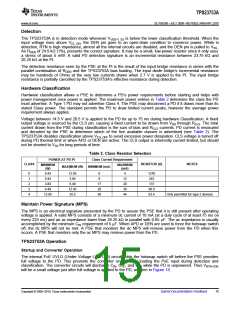
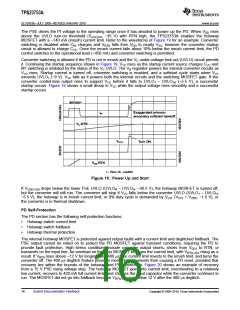
The PSE drives the PI voltage to the operating range once it has decided to power up the PD. When VDD rises
above the UVLO turn-on threshold (VUVLO-R, ~35 V) with RTN high, the TPS23753A enables the hotswap
MOSFET with a ~140 mA (inrush) current limit. Refer to the waveforms of Figure 19 for an example. Converter
switching is disabled while CIN charges and VRTN falls from VDD to nearly VSS, however the converter startup
circuit is allowed to charge CVC. Once the inrush current falls about 10% below the inrush current limit, the PD
control switches to the operational level (~450 mA) and converter switching is permitted.
Converter switching is allowed if the PD is not in inrush and the VC under-voltage lock out (UVLO) circuit permits
it. Continuing the startup sequence shown in Figure 19, VVC rises as the startup current source charges CVC and
M1 switching is inhibited by the status of the VC UVLO. The VB regulator powers the internal converter circuits as
VVC rises. Startup current is turned off, converter switching is enabled, and a softstart cycle starts when VVC
exceeds UVLO1 (~9 V). VVC falls as it powers both the internal circuits and the switching MOSFET gate. If the
converter control-bias output rises to support VVC before it falls to UVLO1 – UVLO1H (~5.5 V), a successful
startup occurs. Figure 19 shows a small droop in VVC while the output voltage rises smoothly and a successful
startup occurs.
10
INRUSH
8
Exaggerated primary-
secondary softstart handoff
IPI
7
6
5
4
3
2
1
0
VC-RTN
VOUT
Turn ON
-0.
-0.
-0.
VDD-RTN
000.0E 10.0E-3 20.0E-3 30.0E-3 40.0E-3 50.0E-3 60.0E-3 70.0E-3 80.0E-3 90.0E-3 100.0E-
t - Time 10 - ms/DIV
Figure 19. Power Up and Start
If VVDD-VSS drops below the lower PoE UVLO (UVLOR – UVLOH, ~30.5 V), the hotswap MOSFET is turned off,
but the converter will still run. The converter will stop if VVC falls below the converter UVLO (UVLO1 – UVLOH,
~5.5 V), the hotswap is in inrush current limit, or 0% duty cycle is demanded by VCTL (VCTL < VZDC, ~1.5 V), or
the converter is in thermal shutdown.
PD Self-Protection
The PD section has the following self-protection functions.
•
•
•
Hotswap switch current limit
Hotswap switch foldback
Hotswap thermal protection
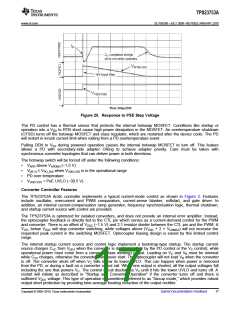
The internal hotswap MOSFET is protected against output faults with a current limit and deglitched foldback. The
PSE output cannot be relied on to protect the PD MOSFET against transient conditions, requiring the PD to
provide fault protection. High stress conditions include converter output shorts, shorts from VDD1 to RTN, or
transients on the input line. An overload on the pass MOSFET engages the current limit, with VRTN-VSS rising as a
result. If VRTN rises above ~12 V for longer than ~400 ms, the current limit reverts to the inrush limit, and turns the
converter off. The 400 ms deglitch feature prevents momentary transients from causing a PD reset, provided that
recovery lies within the bounds of the hotswap and PSE protection. Figure 20 shows an example of recovery
from a 15 V PSE rising voltage step. The hotswap MOSFET goes into current limit, overshooting to a relatively
low current, recovers to 420 mA full current limit, and charges the input capacitor while the converter continues to
run. The MOSFET did not go into foldback because VRTN-VSS was below 12 V after the 400 ms deglitch.
16
Submit Documentation Feedback
Copyright © 2009–2010, Texas Instruments Incorporated

 TI [ TEXAS INSTRUMENTS ]