TPS23753A
SLVS933B –JULY 2009–REVISED JANUARY 2010
www.ti.com
GATE
CS
RS
RCS
CS
5/09/08
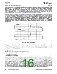
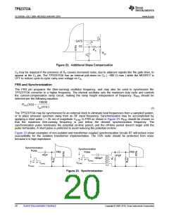
Figure 22. Additional Slope Compensation
CS may be required if the presence of RS causes increased noise, due to adjacent signals like the gate drive, to
appear at the CS pin. The TPS23753A has an internal pull-down on CS ( ~400 Ω max ) while the MOSFET is
OFF to reduce cycle-to-cycle carry-over voltage on CS.
FRS and Synchronization
The FRS pin programs the (free-running) oscillator frequency, and may also be used to synchronize the
TPS23753A converter to a higher frequency. The internal oscillator sets the maximum duty cycle and controls
the current-compensation ramp circuit, making the ramp height independent of frequency. RFRS should be
selected per the following equation.
15000
R
(kΩ) =
FRS
f
(kHz)
SW
(7)
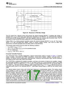
The TPS23753A may be synchronized to an external clock to eliminate beat frequencies from a sampled system,
or to place emission spectrum away from an RF input frequency. Synchronization may be accomplished by
applying a short pulse ( > 25 ns) of magnitude VSYNC to FRS as shown in Figure 23. RFRS should be chosen so
that the maximum free-running frequency is just below the desired synchronization frequency. The
synchronization pulse terminates the potential on-time period, and the off-time period doesn’t begin until the
pulse terminates. A short pulse is preferred to avoid reducing the potential on-time.
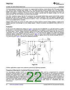
Figure 23 shows examples of non-isolated and transformer-coupled synchronization circuits RT will reduce noise
susceptibility for the isolation transformer implementation. The FRS node should be protected from noise
because it is high impedance.
Synchronization
Synchronization
Pulse
FRS
Pulse
FRS
47pF
47pF
1000pF
TSYNC
VSYNC
TSYNC
1:1
VSYNC
Figure 23. Synchronization
20
Submit Documentation Feedback
Copyright © 2009–2010, Texas Instruments Incorporated

 TI [ TEXAS INSTRUMENTS ]