TPS23753A
www.ti.com
SLVS933B –JULY 2009–REVISED JANUARY 2010
APPLICATIONS
Classic PoE Overview
The following text is intended as an aid in understanding the operation of the TPS23753A but not as a substitute
for the actual IEEE 802.3at standard. The IEEE 802.3at standard is an update to IEEE 802.3-2008 clause 33
(PoE), adding high-power options and enhanced classification. Generally speaking, a device compliant to IEEE
802.3-2008 will be referred to as a Type 1 device, and devices with high power or enhanced classification will be
referred to as Type 2 devices. The TPS23753A is intended to power type 1 devices (up to 13W) and is fully
compliant to IEEE 802.3at for hardware classes 0 - 3. Standards change and should always be referenced when
making design decisions.
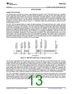
The IEEE 802.3at standard defines a method of safely powering a PD (powered device) over a cable, and then
removing power if a PD is disconnected. The process proceeds through an idle state and three operational states
of detection, classification, and operation. The PSE leaves the cable unpowered (idle state) while it periodically
looks to see if something has been plugged in; this is referred to as detection. The low power levels used during
detection are unlikely to damage devices not designed for PoE. If a valid PD signature is present, the PSE may
inquire how much power the PD requires; this is referred to as (hardware) classification. Only type 2 PSEs are
required to do hardware classification. The PD may return the default 13W current-encoded class, or one of four
other choices. The PSE may then power the PD if it has adequate capacity. Once started, the PD must present
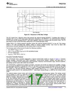
the maintain power signature (MPS) to assure the PSE that it is still present. The PSE monitors its output for a
valid MPS, and turns the port off if it loses the MPS. Loss of the MPS returns the PSE to the idle state. Figure 16
shows the operational states as a function of PD input voltage.
Shut-
down
Classify
Normal Operation
Detect
0
2.7
10.1 14.5
20.5
30
PI Voltage (V)
36
57
42
3/06/08
Figure 16. IEEE 802.3-2005 (Type 1) Operational States
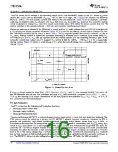
The PD input is typically an RJ-45 eight-lead connector which is referred to as the power interface (PI). PD input
requirements differ from PSE output requirements to account for voltage drops in the cable and operating
margin. The IEEE 802.3at standard uses a cable resistance of 20 Ω for type 1 devices to derive the voltage limits
at the PD based on the PSE output voltage requirements. Although the standard specifies an output power of
15.4 W at the PSE, only 13 W is available at the PI due to the worst-case power loss in the cable. The PSE can
apply voltage either between the RX and TX pairs (pins 1–2 and 3–6 for 10baseT or 100baseT), or between the
two spare pairs (4–5 and 7–8). The PSE may only apply voltage to one set of pairs at a time. The PD uses input
diode bridges to accept power from any of the possible PSE configurations. The voltage drops associated with
the input bridges create a difference between the standard limits at the PI and the TPS23753A specifications.
The PSE is permitted to disconnect a PD if it draws more than its maximum class power over a one second
interval. A type 1 PSE compliant to IEEE 802.3at is required to limit current to between 400 mA and 450 mA
during powered operation, and it must disconnect the PD if it draws this current for more than 75 ms. Class 0
and 3 PDs may draw up to 400 mA peak currents for up to 50 ms. The PSE may set lower output current limits
based on the PD’s declared power requirements.
Copyright © 2009–2010, Texas Instruments Incorporated
Submit Documentation Feedback
13

 TI [ TEXAS INSTRUMENTS ]