ꢀ
ꢁꢂ
ꢃ
ꢄꢄ
ꢅ
ꢆꢇ
www.ti.com
SLOS407D − FEBRUARY 2003 − REVISED AUGUST 2004
SD OPERATION
The TPA3004D2 employs a shutdown mode of operation designed to reduce supply current (I ) to the
CC
absolute minimum level during periods of nonuse for power conservation. The SD input terminal should be held
high (see specification table for trip point)during normal operation when the amplifier is in use. Pulling SD low
causes the outputs to mute and the amplifier to enter a low-current state, I
left unconnected, because amplifier operation would be unpredictable.
= 10 µA. SD should never be
CC(SD)
POWER-OFF POP REDUCTION
For the best power-off pop performance, the amplifier should be placed in the shutdown mode prior to removing
the power supply voltage.
Another method to reduce power-off pop is implemented in the hardware. A 100-µF − 150-µF capacitor can
be added to the AV
terminal in parallel with the 100-nF capacitor shown in Figure 35. The additional
DD
capacitance holds up the regulator voltage for a longer period of time and results in smaller power-off pop.
USING LOW-ESR CAPACITORS
Low-ESR capacitors are recommended throughout this application section. A real (as opposed to ideal)
capacitor can be modeled simply as a resistor in series with an ideal capacitor. The voltage drop across this
resistor minimizes the beneficial effects of the capacitor in the circuit. The lower the equivalent value of this
resistance the more the real capacitor behaves like an ideal capacitor.
SHORT-CIRCUIT PROTECTION
The TPA3004D2 has short circuit protection circuitry on the outputs that prevents damage to the device during
output-to-output shorts, output-to-GND shorts, and output-to-V
shorts. When a short-circuit is detected on
CC
the outputs, the part immediately disables the output drive. This is a latched fault and must be reset by cycling
the voltage on the SD pin to a logic low and back to the logic high state for normal operation. This will clear the
short-circuit flag and allow for normal operation if the short was removed. If the short was not removed, the
protection circuitry will again activate. The trip-point for the short-circuit protection is nominally set at 8 A.
For V
> 15 V, two Schottky diodes are required to provide short-circuit protection. The diodes should be
CC
placed as closes to the TPA3004D2 as possible, with the anodes connected to PGND and the cathodes
connected to OUTP and OUTN as shown in the application circuit schematic. The diodes should have a forward
voltage rating of 0.5 V at a minimum of 1 A output current an a dc blocking voltage rating of at least 30 V. The
diodes must also be rated to operate at a junction temperature of 150°C. If V
not required for short circuit protection.
< 15 V, the schottky diodes are
CC
If short-circuit protection is not required, the Schottky diodes may be omitted.
THERMAL PROTECTION
Thermal protection on the TPA3004D2 prevents damage to the device when the internal die temperature
exceeds 150°C. There is a 15 degree tolerance on this trip point from device to device. Once the die
temperature exceeds the thermal set point, the device enters into the shutdown state and the outputs are
disabled. This is not a latched fault. The thermal fault is cleared once the temperature of the die is reduced by
20°C. The device begins normal operation at this point with no external system interaction.
THERMAL CONSIDERATIONS: OUTPUT POWER AND MAXIMUM AMBIENT TEMPERATURE
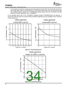
To calculate the maximum ambient temperature, the following equation may be used:
T
= T – Θ P
JA Dissipated
Amax
J
where: T = 125°C
J
Θ
= 19°C/W
(2-Layer PCB, 5 sq. in. copper, see Figure 47)
JA
(8)
(The derating factor for the 48-pin PHP package is given in the dissipation rating table.)
To estimate the power dissipation, the following equation may be used:
32

 TI [ TEXAS INSTRUMENTS ]