www.ti.com
ꢀ ꢁꢂ ꢃꢄꢄ ꢅꢆ ꢇ
SLOS407D − FEBRUARY 2003 − REVISED AUGUST 2004
BASIC MEASUREMENT SYSTEM
This application note focuses on methods that use the basic equipment listed below:
D
D
D
D
D
D
D
D
D
Audio analyzer or spectrum analyzer
Digital multimeter (DMM)
Oscilloscope
Twisted pair wires
Signal generator
Power resistor(s)
Linear regulated power supply
Filter components
EVM or other complete audio circuit
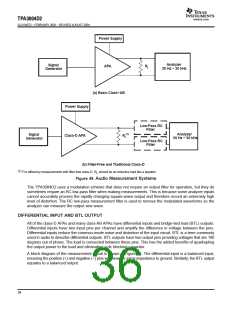
Figure 49 shows the block diagrams of basic measurement systems for class-AB and class-D amplifiers. A sine
wave is normally used as the input signal since it consists of the fundamental frequency only (no other
harmonics are present). An analyzer is then connected to the APA output to measure the voltage output. The
analyzer must be capable of measuring the entire audio bandwidth. A regulated dc power supply is used to
reduce the noise and distortion injected into the APA through the power pins. A System Two audio measurement
system (AP-II) (Reference 1) by Audio Precision includes the signal generator and analyzer in one package.
The generator output and amplifier input must be ac-coupled. However, the EVMs already have the ac-coupling
capacitors, (C ), so no additional coupling is required. The generator output impedance should be low to avoid
IN
attenuating the test signal, and is important since the input resistance of APAs is not very high (about 10 kΩ).
Conversely the analyzer-input impedance should be high. The output impedance, R
in the hundreds of milliohms and can be ignored for all but the power-related calculations.
, of the APA is normally
OUT
Figure 49(a) shows a class-AB amplifier system. They take an analog signal input and produce an analog signal
output. These amplifier circuits can be directly connected to the AP-II or other analyzer input.
This is not true of the class-D amplifier system shown in Figure 49(b), which requires low pass filters in most
cases in order to measure the audio output waveforms. This is because it takes an analog input signal and
converts it into a pulse-width modulated (PWM) output signal that is not accurately processed by some
analyzers.
35

 TI [ TEXAS INSTRUMENTS ]