www.ti.com
ꢀ ꢁꢂ ꢃꢄꢄ ꢅꢆ ꢇ
SLOS407D − FEBRUARY 2003 − REVISED AUGUST 2004
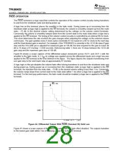
SD = 0 V
GND
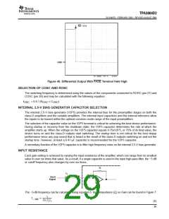
Figure 45. Differential Output With FADE Terminal Held High
SELECTION OF COSC AND ROSC
The switching frequency is determined using the values of the components connected to ROSC (pin 27) and
COSC (pin 28) and may be calculated with the following equation:
f
= 6.6 / (R
× C
)
OSC
OSC
OSC
INTERNAL 2.5-V BIAS GENERATOR CAPACITOR SELECTION
The internal 2.5-V bias generator (V2P5) provides the internal bias for the preamplifier stages on both the
class-D amplifiers and the variable amplifiers. The external input capacitors and this internal reference allow
the inputs to be biased within the optimal common-mode range of the input preamplifiers.
The selection of the capacitor value on the V2P5 terminal is critical for achieving the best device performance.
During startup or recovery from the shutdown state, the V2P5 capacitor determines the rate at which the
amplifier starts up. When the voltage on the V2P5 capacitor equals 0.75xV2P5, or 75% of its final value, the
device turns on and the class-D outputs start switching. The startup time is not critical for the best depop
performance since any pop sound that is heard is the result of the class-D outputs switching on and not the
startup time. However, at least a 0.47-µF capacitor is recommended for the V2P5 capacitor.
A secondary function of the V2P5 capacitor is to filter high frequency noise on the internal 2.5-V bias generator.
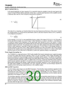
INPUT RESISTANCE
Each gain setting is achieved by varying the input resistance of the amplifier, which can range from its smallest
value to over six times that value. As a result, if a single capacitor is used in the input high-pass filter, the −3 dB
or cutoff frequency also changes by over six times.
Z
f
C
i
Z
i
IN
Input
Signal
The −3-dB frequency can be calculated using equation 5. Input impedance (Z ) vs Gain can be found in Figure 7.
i
1
f
+
*3dB
2p Z C
(5)
i i
29

 TI [ TEXAS INSTRUMENTS ]