ꢀ
ꢁꢂ
ꢃ
ꢄꢄ
ꢅ
ꢆ
ꢇ
www.ti.com
SLOS407D − FEBRUARY 2003 − REVISED AUGUST 2004
FADE OPERATION
The FADE terminal is a logic input that controls the operation of the volume control circuitry during transitions
to and from the shutdown state and during power-up.
A logic low on this terminal, places the amplifier in the fade mode. During power-up or recovering from the
shutdown state (a logic high is applied to the SD terminal), the volume is smoothly ramped up from the mute
state, −75 dB, to the desired volume setting determined by the voltage on the volume control terminals.
Conversely, the volume is smoothly ramped down from the current state to the mute state when a logic low is
applied to the SD terminal. The timing of the volume control circuitry is controlled by an internal 60-Hz clock.
This clock determines the rate at which the gain changes when adjusting the voltage on the external volume
control pins. The gain updates every 4 clock cycles (nominally 67 ms based on a 60 Hz clock) to the next step
until the final desired gain is reached. For example, if the TPA3004D2 is currently in the +0.53 db class-D gain
step and the VOLUME pin is adjusted for maximum gain at +36 dB, the time required for the gain to reach 36
dB is 14 steps x 67 ms/step = 0.938 seconds. Referencing table 1, there are 14 steps between the +0.53 dB
gain step and the maximum gain step of +36 dB.
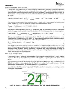
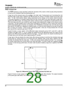
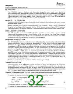
Figure 44 shows a scope capture of the differential output (measured across OUT+ and OUT−) with the
amplifier in the fade mode. A 1 V dc voltage was applied across the differential inputs and a logic low was
pp
applied to the SD terminal at the time defined in the figure. The figure depicts the outputs transitioning from
one gain step to the next lower step at approximately 67 ms/step.
A logic high on this pin disables the volume fade effect during transitions to and from the shutdown state and
during power-up. During power-up or recovering from the shutdown state (a logic high is applied to the SD
terminal), the transition from the mute state, −75 dB, to the desired volume setting is less than 1 ms. Conversely,
the volume ramps down from current state to the mute state within 1 ms when a logic low is applied to the SD
terminal. For the best pop performance, the fade mode should be enabled (a logic low is applied to the FADE
terminal).
SD = 0V
GND
Figure 44. Differential Output With FADE (Terminal 30) Held Low
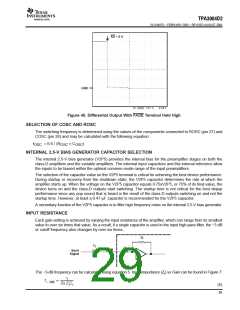
Figure 45 shows a scope capture of the differential output with the fade effect disabled. The outputs transition
to the lowest gain state within 1ms of applying a logic low to the SD terminal.
28

 TI [ TEXAS INSTRUMENTS ]