www.ti.com
ꢀ ꢁꢂ ꢃꢄꢄ ꢅꢆ ꢇ
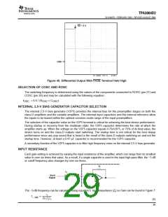
SLOS407D − FEBRUARY 2003 − REVISED AUGUST 2004
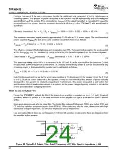
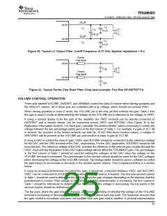
33 µH
OUTP
OUTN
C
2
L
1
C
1
0.1 µF
0.47 µF
33 µH
C
3
L
2
0.1 µF
Figure 40. Typical LC Output Filter, Cutoff Frequency of 27 kHz, Speaker Impedance = 8 Ω
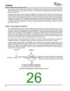
Ferrite
Chip Bead
OUTP
1 nF
Ferrite
Chip Bead
OUTN
1 nF
Figure 41. Typical Ferrite Chip Bead Filter (Chip bead example: Fair-Rite 2512067007Y3)
VOLUME CONTROL OPERATION
Three pins labeled VOLUME, VARDIFF, and VARMAX control the class-D volume when driving speakers and
the VAROUT volume. All of these pins are controlled with a dc voltage, which should not exceed VREF.
When driving speakers in class-D mode, the VOLUME pin is the only pin that controls the gain. Table 1 lists
the gain in class-D mode as determined by the voltage on the VOLUME pin in reference to the voltage on VREF.
If using a resistor divider to fix the gain of the amplifier, the VREF terminal can be directly connected to
AVDDREF and a resistor divider can be connected across VREF and REFGND. (See Figure 35 in the
Application Information section). For fixed gain, calculate the resistor divider values necessary to center the
voltage between the two percentage points given in the first column of Table 1. For example, if a gain of 10.7 dB
is desired, the resistors in the divider network can both be 10 kΩ. With these resistor values, a voltage of
50%*VREF will be present at the VOLUME pin and result in a class-D gain of 10.7 dB.
If using a DAC to control the class-D gain, VREF and REFGND should be connected to the reference voltage
for the DAC and the GND terminal of the DAC, respectively. For the DAC application, AVDDREF would be left
unconnected. The reference voltage of the DAC provides the reference to the internal gain circuitry through the
VREF input and any fluctuations in the DAC output voltage will not affect the TPA3004D2 gain. The percentages
in the first column of Table 1 should be used for setting the voltages of the DAC when the voltage on the
VOLUME terminal is increased. The percentages in the second column should be used for the DAC voltages
when decreasing the voltage on the VOLUME terminal. Two lookup tables should be used in software to control
the gain based on an increase or decrease in the desired system volume. This is explained further in a section
below.
If using an analog potentiometer to control the gain, it should be connected between VREF and REFGND.
VREF can be connected to AVDDREF or an external voltage source, if desired. The first and second column
in Table 1 should be used to determine the point at which the gain changes depending on the direction that the
potentiometer is turned. If the voltage on the center tap of the potentiometer is increasing, the first column in
Table 1 should be referenced to determine the trip points. If the voltage is decreasing, the trip points in the
second column should be referenced.
The trip point, where the gain actually changes, is different depending on whether the voltage on the VOLUME
terminal is increasing or decreasing as a result of hysteresis about each trip point. The hysteresis ensures that
the gain control is monotonic and does not oscillate from one gain step to another. A pictorial representation
25

 TI [ TEXAS INSTRUMENTS ]