ꢀ
ꢁ
ꢂ
ꢃ
ꢄꢄ
ꢅ
ꢆꢇ
www.ti.com
SLOS407D − FEBRUARY 2003 − REVISED AUGUST 2004
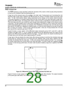
of the volume control can be found in Figure 43. The graph focuses on three gain steps with the trip points
defined in the first and second columns of Table 1 for class-D gain. The dotted lines represent the hysteresis
about each gain step.
The timing of the volume control circuitry is controlled by an internal 60 Hz clock. This clock determines the rate
at which the gain changes when adjusting the voltage on the external volume control pins. The gain updates
every 4 clock cycles (nominally 67 ms based on a 60 Hz clock) to the next step until the final desired gain is
reached. For example, if the TPA3004D2 is currently in the +0.53 db class-D gain step and the VOLUME pin
is adjusted for maximum gain at +36 dB, the time required for the gain to reach 36dB is 14 steps x 67ms/step
= 0.938 seconds. Referencing table 1, there are 14 steps between the +0.53 dB gain step and the maximum
gain step of +36 dB.
VARDIFF AND VARMAX OPERATION
The TPA3004D2 allows the user to specify a difference between the class-D gain and VAROUT gain. This is
desirable to avoid any listening discomfort when plugging in headphones. When interfacing with the variable
outputs, the VARDIFF and VARMAX pins control the VAROUT channel gain proportional to the gain set by the
voltage on the VOLUME pin. When VARDIFF=0 V, the difference between the class-D gain and the VAROUT
gain is 16 dB. As the voltage on the VARDIFF terminal is increased, the VAROUT channel gain decreases.
Internal to the TPA3004D2 device, the voltage on the VARDIFF terminal is subtracted from the voltage on the
VOLUME terminal and this value is used to determine the VAROUT gain.
Some audio systems require that the gain be limited in the VAROUT mode to a level that is comfortable for
headphone listening. The VARMAX terminal controls the maximum gain for the VAROUT channels.
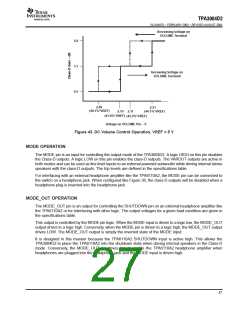
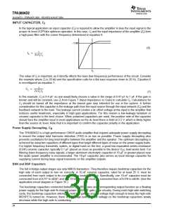
The functionality of the VARDIFF and VARMAX pin are combined to fix the VAROUT channel gain. A block
diagram of the combined functionality is shown in Figure 42. The value obtained from the block diagram for
VAROUT_VOLUME is a DC voltage that can be used in conjunction with Table 2 to determine the VAROUT
channel gain. Table 2 lists the gain in VAROUT mode as determined by the VAROUT_VOLUME voltage in
reference to the voltage on VREF.
VARDIFF (V)
VARMAX (V)
−
Is VARMAX>
(VOLUME−VARDIFF)
?
YES
+
VOLUME−VARDIFF
VOLUME (V)
VAROUT_VOLUME (V) = VOLUME (V) − VARDIFF (V)
NO
VAROUT_VOLUME (V) = VARMAX (V)
Figure 42. Block Diagram of VAROUT Volume Control
26

 TI [ TEXAS INSTRUMENTS ]