ꢀ
ꢁꢂ
ꢃ
ꢄꢄ
ꢅ
ꢆꢇ
www.ti.com
SLOS407D − FEBRUARY 2003 − REVISED AUGUST 2004
Damage may occur if the voice coil cannot handle the additional heat generated from the high-frequency
switching current. The amount of power dissipated in the speaker may be estimated by first considering the
overall efficiency of the system. If the on-resistance (r
) of the output transistors is considered to cause the
ds(on)
dominant loss in the system, then the maximum theoretical efficiency for the TPA3004D2 with an 8-Ω load is
as follows:
Efficiency (theoretical, %) + R ńǒRL ) r
Ǔ
100% + 8ń(8 ) 0.58) 100% + 93.24%
L
ds(on)
(1)
The maximum measured output power is approximately 7.5 W with an 12-V power supply. The total theoretical
power supplied (P ) for this worst-case condition would therefore be as follows:
(total)
P
+ P ńEfficiency + 7.5 W ń 0.9324 + 8.04 W
(total)
O
(2)
The efficiency measured in the lab using an 8-Ω speaker was 89%. The power not accounted for as dissipated
across the r may be calculated by simply subtracting the theoretical power from the measured power:
ds(on)
Other losses + P
(measured) * P
(theoretical) + 8.43 * 8.04 + 0.387 W
(total)
(total)
(3)
The quiescent supply current at 14 V is measured to be 14.3 mA. It can be assumed that the quiescent current
encapsulates all remaining losses in the device, i.e., biasing and switching losses. It may be assumed that any
remaining power is dissipated in the speaker and is calculated as follows:
P
+ 0.387 W * (14 V 14.3 mA) + 0.19 W
(dis)
(4)
Note that these calculations are for the worst-case condition of 7.5 W delivered to the speaker. Since the 0.19 W
is only 2.5% of the power delivered to the speaker, it may be concluded that the amount of power actually
dissipated in the speaker is relatively insignificant. Furthermore, this power dissipated is well within the
specifications of most loudspeaker drivers in a system, as the power rating is typically selected to handle the
power generated from a clipping waveform.
When to use an Output Filter
Design the TPA3004D2 without the filter if the traces from amplifier to speaker are short (< 1 inch). Powered
speakers, where the speaker is in the same enclosure as the amplifier, is a typical application for class-D without
a filter.
Most applications require a ferrite bead filter. The ferrite filter reduces EMI around 1 MHz and higher (FCC and
CE only test radiated emissions greater than 30 MHz). When selecting a ferrite bead, choose one with high
impedance at high frequencies, but very low impedance at low frequencies.
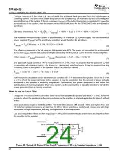
Use a LC output filter if there are low frequency (<1 MHz) EMI sensitive circuits and/or there are long wires from
the amplifier to the speaker.
15 µH
OUTP
C
2
L
1
C
1
0.22 µF
1 µF
15 µH
OUTN
C
3
L
2
0.22 µF
Figure 39. Typical LC Output Filter, Cutoff Frequency of 27 kHz, Speaker Impedance = 4 Ω
24

 TI [ TEXAS INSTRUMENTS ]