TMS320TCI6487
TMS320TCI6488
Communications Infrastructure Digital Signal Processor
www.ti.com
SPRS358F–APRIL 2007–REVISED AUGUST 2008
8.14 Timers
The timers can be used to: time events, count events, generate pulses, interrupt the CPU, and send
synchronization event so the EDMA3 channel controller.
8.14.1 Timers Device-Specific Information
The device has six general purpose timers: Timer0 to Timer5, each of which can be configured as a
general purpose timer or a watchdog timer. When configured as a general-purpose timer, each timer can
be programmed as a 64-bit timer or as two separate 32-bit timers.
Each timer is made up of two 32-bit counters: a high counter and a low counter. The timer pinout is
described in the next section.
8.14.1.1 Timer I/O Selection
Not all timer inputs and outputs are pinned out of the device. The six timers have a flexible (e.g. software
controlled) selection of timer inputs and outputs. At the chip level there are four timer pins, two input pins
(TIMI[1:0]) and two output pins (TIMO[1:0]). Each timer input can be configured to be driven by either of
the timer input pins, or by an FSYNC event (FSEVT[3:2]). Each output pin can be driven by any of the
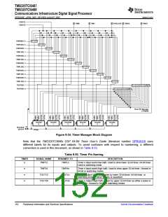
timer outputs. This is programmable through software via the Timer Pin Manager Block, as shown in the
Figure 8-34. Not shown in the figure is the logic that gates the timer resets that are routed to the PLL
controller, shown in Figure 8-35.
Submit Documentation Feedback
Peripheral Information and Electrical Specifications
151

 TI [ TEXAS INSTRUMENTS ]