TMS320DM6437
Digital Media Processor
www.ti.com
SPRS345B–NOVEMBER 2006–REVISED MARCH 2007
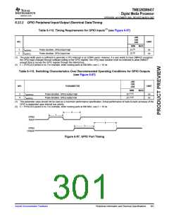
6.23.2 GPIO Peripheral Input/Output Electrical Data/Timing
Table 6-112. Timing Requirements for GPIO Inputs(1) (see Figure 6-57)
-400
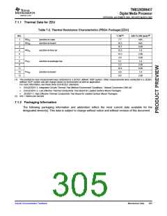
-500
-600
NO.
UNIT
MIN
MAX
1
2
tw(GPIH)
tw(GPIL)
Pulse duration, GP[x] input high
Pulse duration, GP[x] input low
2C(2)
2C(2)
ns
ns
(1) The pulse width given is sufficient to generate a CPU interrupt or an EDMA event. However, if a user wants to have DM6437 recognize
the GP[x] input changes through software polling of the GPIO register, the GP[x] input duration must be extended to allow DM6437
enough time to access the GPIO register through the internal bus.
(2) C = SYSCLK3 period in ns. For example, when running parts at 600 MHz, use C = 10 ns.
Table 6-113. Switching Characteristics Over Recommended Operating Conditions for GPIO Outputs
(see Figure 6-57)
-400
-500
-600
NO.
PARAMETER
UNIT
MIN
MAX
3
4
tw(GPOH)
tw(GPOL)
Pulse duration, GP[x] output high
Pulse duration, GP[x] output low
2C(1)(2)
2C(1)(2)
ns
ns
(1) This parameter value should not be used as a maximum performance specification. Actual performance of back-to-back accesses of the
GPIO is dependent upon internal bus activity.
(2) C = SYSCLK3 period in ns. For example, when running parts at 600 MHz, use C = 10 ns.
2
1
GP[x]
Input
4
3
GP[x]
Output
Figure 6-57. GPIO Port Timing
Submit Documentation Feedback
Peripheral Information and Electrical Specifications
301

 TI [ TEXAS INSTRUMENTS ]