TMS320DM6437
Digital Media Processor
www.ti.com
SPRS345B–NOVEMBER 2006–REVISED MARCH 2007
4 System Interconnect
On the DM6437 device, the C64x+ Megamodule, the EDMA3 transfer controllers, and the system
peripherals are interconnected through a switch fabric architecture (see Figure 4-1). The switch fabric is
composed of multiple switched central resources (SCRs) and multiple bridges. The SCRs establish
low-latency connectivity between master peripherals and slave peripherals. Additionally, the SCRs provide
priority-based arbitration and facilitate concurrent data movement between master and slave peripherals.
Through an SCR, the DSP subsystem can send data to the DDR2 Memory Controller without affecting a
data transfer between the EMAC and L2 memory. Bridges are mainly used to perform bus-width
conversion as well as bus operating frequency conversion. For example, in Figure 4-1, Bridge 6 performs
a frequency conversion between a bus operating at DSP/3 clock rate and a bus operating at DSP/6 clock
rate. Furthermore, Bridge 5 performs a bus-width conversion between a 64-bit bus and a 32-bit bus.
The C64x+ Megamodule, the EDMA3 transfer controllers (EDMA3TC[2:0]), and the various system
peripherals can be classified into two categories: master peripherals and slave peripherals. Master
peripherals are typically capable of initiating read and write transfers in the system and do not rely on the
EDMA3 or on the CPU to perform transfers to and from them. The system master peripherals include the
C64x+ Megamodule, the EDMA3 transfer controllers, VLYNQ, EMAC, HPI, PCI, and VPSS. Not all master
peripherals may connect to all slave peripherals. The supported connections are designated by "Y" in
Table 4-1.
Table 4-1. System Connection Matrix
SLAVE PERIPHERALS/MODULES
MASTER
PERIPHERALS/MODULES
DDR2
MEMORY
CONTROLLER
C64x+
SDMA
PCI
SCR2, SCR6,
SCR4(1)
(MASTER BACK-END I/F)
SCR7, SCR8(1)
C64x+ MDMA
–
–
Y
Y
Y
Y
Y
Y
Y
–
–
–
–
–
–
–
Y
–
VPSS
PCI (SLAVE BACK-END I/F)
Y
Y
Y
Y
Y
Y
Y
Y
Y
Y
Y
Y
VLYNQ
EMAC
HPI
EDMA3TC's
(EDMA3TC2/TC1/TC0)
Y
–
Y
–
Y
–
Y
Y
Y
Y
C64x+ CFG
(1) All the peripherals/modules that support a connection to SCR2, SCR4, SCR6, SCR7, and SCR8 have access to all peripherals/modules
connected to those respective SCRs.
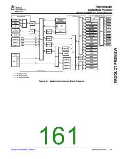
4.1 System Interconnect Block Diagram
Figure 4-1 displays the DM6437 system interconnect block diagram. The following is a list that helps in
the interpretation of this diagram:
•
•
•
The direction of the arrows indicates either a bus master or bus slave.
The arrow originates at a bus master and terminates at a bus slave.
The direction of the arrows does not indicate the direction of data flow. Data flow is typically
bi-directional for each of the documented bus paths.
•
•
The pattern of each arrow's line indicates the clock rate at which it is operating— i.e., either DSP/3,
DSP/6, or MXI/CLKIN clock rate.
A peripheral may have multiple instances shown in Figure 4-1 for the following reason:
–
The peripheral/module has master port(s) for data transfers, as well as slave port(s) for register
access, data access, and/or memory access. Examples of these peripherals are C64x+
Megamodule, EDMA3, VPSS, VLYNQ, HPI, EMAC, and PCI.
160
System Interconnect
Submit Documentation Feedback

 TI [ TEXAS INSTRUMENTS ]