TMS320DM6437
Digital Media Processor
www.ti.com
SPRS345B–NOVEMBER 2006–REVISED MARCH 2007
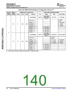
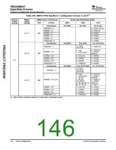
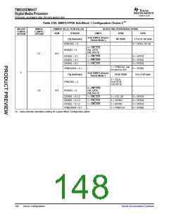
The following is an example of how to read Table 3-43 through Table 3-49 using Sub-Block 0 Minor
Configuration B6 as an example:
•
•
The PINMUX Selection Fields columns indicate that Sub-Block 0 Minor Configuration Option B6 is
selected through setting PINMUX1.PCIEN = 0, PINMUX0.AEM = 1, PINMUX0.AEAW = 4, CCDCSEL
= 1, HVDSEL = 0 or 1 (based on the system’s need for VPFE control signals VD and HD), CWENSEL
= 0 (mandatory setting), CFLDSEL = 0 or 1 (based on the system’s need for VPFE control signal
C_FIELD), CI10SEL = 0 (mandatory), CI32SEL = 0 (mandatory), CI54SEL = 0 (mandatory), and
CI76SEL = 0 (mandatory).
The Resulting Peripherals/Pins columns show the functional pins resulting from the PINMUX setting.
For example, PINMUX0.CCDCSEL = 1 gives the user the PCLK and YI[7:0] pins for the VPFE.
PINMUX0.HVDSEL = 1 gives the user VD and HD pins for VPFE, while HVDSEL = 0 gives the user 2
GP pins.
144
Device Configurations
Submit Documentation Feedback

 TI [ TEXAS INSTRUMENTS ]