TMS320C6678
Multicore Fixed and Floating-Point Digital Signal Processor
SPRS691D—April 2013
www.ti.com
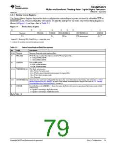
3.3.1 Device Status Register
The Device Status Register depicts the device configuration selected upon a power-on reset by either the POR or
RESETFULL pin. Once set, these bits will remain set until the next power-on reset. The Device Status Register is
shown in Figure 3-1 and described in Table 3-3.
Figure 3-1
Device Status Register
31
18
17
PACLKSEL
16
PCIESSEN
R-x
15
14
13
1
0
Reserved
R-0
PCIESSMODE[1:0
R/W-xx
BOOTMODE[12:0]
R/W-xxxxxxxxxxxx
LENDIAN
R-x (1)
Legend: R = Read only; RW = Read/Write; -n = value after reset
1 x indicates the bootstrap value latched via the external pin
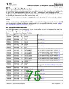
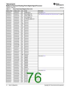
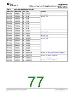
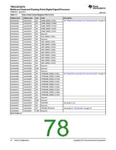
Table 3-3
Device Status Register Field Descriptions
Bit
Field
Description
31-18 Reserved
Reserved. Read only, writes have no effect.
17
PACLKSEL
PA Clock select to select the reference clock for PA Sub-System PLL
0 = Selects CORECLK(P/N)
1 = Selects PASSCLK(P/N)
16
PCIESSEN
PCIe module enable
0 = PCIe module disabled
1 = PCIe module enabled
15-14 PCIESSMODE[1:0] PCIe Mode selection pins
00b = PCIe in End-point mode
01b = PCIe in Legacy End-point mode (support for legacy INTx)
10b = PCIe in Root complex mode
11b = Reserved
13-1
0
BOOTMODE[12:0] Determines the bootmode configured for the device. For more information on bootmode, refer to Section 2.5 ‘‘Boot
Modes Supported and PLL Settings’’ on page 28 and see the Bootloader for the C66x DSP User Guide in 2.10 ‘‘Related
Documentation from Texas Instruments’’ on page 73
LENDIAN
Device Endian mode (LENDIAN) — Shows the status of whether the system is operating in Big Endian mode or Little
Endian mode.
0 = System is operating in Big Endian mode
1 = System is operating in Little Endian mode
End of Table 3-3
Copyright 2013 Texas Instruments Incorporated
Device Configuration 79

 TI [ TEXAS INSTRUMENTS ]