TMS320C6678
Multicore Fixed and Floating-Point Digital Signal Processor
SPRS691D—April 2013
www.ti.com
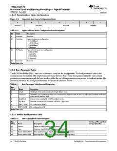
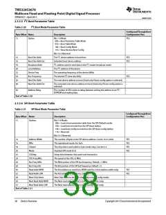
2.5.3.5 I2C Boot Parameter Table
Table 2-20
I2C Boot Mode Parameter Table
Configured Through Boot
Configuration Pins
Byte Offset Name
Description
12
Option
Bits 1-0 Mode
YES
00b = Boot Parameter Table Mode
01b = Boot Table Mode
10b = Boot Config Mode
11b = Slave Receive Boot Config
Bits 15-2 Reserved
14
16
18
20
22
24
26
28
Boot Dev Addr
Boot Dev Addr Ext
Broadcast Addr
Local Address
Device Freq
The I2C device address to boot from
YES
Extended boot device address
YES
I2C address used to send data in the I2C master broadcast mode.
The I2C address of this device
-
-
The operating frequency of the device (MHz)
The desired I2C data rate (kHz)
-
Bus Frequency
Next Dev Addr
Next Dev Addr Ext
YES
The next device address to boot (Used only if boot config option is selected)
-
-
The extended next device address to boot (Used only if boot config option is
selected)
30
Address Delay
The number of CPU cycles to delay between writing the address to an I2C
EEPROM and reading data.
-
End of Table 2-20
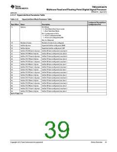
2.5.3.6 SPI Boot Parameter Table
Table 2-21
SPI Boot Mode Parameter Table
Configured Through Boot
Configuration Pins
Byte Offset Name
Description
12
Options
Bits 1-0 Modes
-
00b = Load a boot parameter table from the SPI (Default mode)
01b = Load boot records from the SPI (boot tables)
10b = Load boot config records from the SPI (boot config tables)
11b = Reserved
Bits 15-2 Reserved
14
16
18
20
22
24
26
28
30
32
28
30
32
Address Width
NPin
The number of bytes in the SPI device address. Can be 16 or 24 bit
The operational mode, 4or 5pin
YES
YES
Chipsel
The chip select used (valid in 4 pin mode only). Can be 0-3.
Standard SPI mode (0-3)
YES
Mode
YES
C2Delay
Setup time between chip assert and transaction
The speed of the CPU, in MHz
-
CPU Freq MHz
Bus Freq, MHz
Bus Freq, kHz
Read Addr MSW
Read Addr LSW
Next Chip Select
Next Read Addr MSW
Next Read Addr LSW
-
The MHz portion of the SPI bus frequency. Default = 5 MHz
The kHz portion of the SPI buf frequency. Default = 0
The first address to read from, MSW (valid for 24 bit address width only)
The first address to read from, LSW
-
-
YES
YES
Next Chip Select to be used (Used only in boot Config mode)
The Next read address (used in boot config mode only)
The Next read address (used in boot config mode only)
-
-
-
End of Table 2-21
38
Device Overview
Copyright 2013 Texas Instruments Incorporated

 TI [ TEXAS INSTRUMENTS ]