TMS320C6678
Multicore Fixed and Floating-Point Digital Signal Processor
SPRS691D—April 2013
www.ti.com
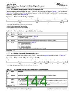
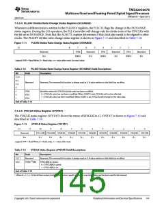
7.5.2.4 PLLDIV Divider Ratio Change Status Register (DCHANGE)
Whenever a different ratio is written to the PLLDIVn registers, the PLLCTL flags the change in the DCHANGE
status register. During the GO operation, the PLL Controller will change only the divide ratio of the SYSCLKs with
the bit set in DCHANGE. Note that the ALNCTL register determines if that clock also needs to be aligned to other
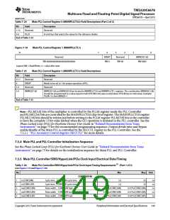
clocks. The PLLDIV divider ratio change status register is shown in Figure 7-11 and described in Table 7-18.
Figure 7-11
PLLDIV Divider Ratio Change Status Register (DCHANGE)
31
8
7
6
5
4
3
2
1
0
Reserved
R-0
SYS8
R/W-0
Reserved
R-0
SYS5
R/W-0
Reserved
R-0
SYS2
R/W-0
Reserved
R-0
Legend: R/W = Read/Write; R = Read only; -n = value after reset, for reset value
Table 7-18
PLLDIV Divider Ratio Change Status Register (DCHANGE) Field Descriptions
Bit
31-8
6-5
3-2
0
Field Description
Reserved
Reserved. The reserved bit location is always read as 0. A value written to this field has no effect.
7
SYS8
SYS5
SYS2
Identifies when the SYSCLKn divide ratio has been modified.
0 = SYSCLKn ratio has not been modified. When GOSET is set, SYSCLKn will not be affected.
1 = SYSCLKn ratio has been modified. When GOSET is set, SYSCLKn will change to the new ratio.
4
1
End of Table 7-18
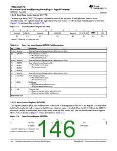
7.5.2.5 SYSCLK Status Register (SYSTAT)
The SYSCLK status register (SYSTAT) shows the status of SYSCLK[11:1]. SYSTAT is shown in Figure 7-12 and
described in Table 7-19.
Figure 7-12
SYSCLK Status Register (SYSTAT)
31
11
10
SYS11ON SYS10ON SYS9ON SYS8ON SYS7ON SYS6ON SYS5ON SYS4ON SYS3ON SYS2ON SYS1ON
R-1 R-1 R-1 R-1 R-1 R-1 R-1 R-1 R-1 R-1 R-1
9
8
7
6
5
4
3
2
1
0
Reserved
R-n
Legend: R/W = Read/Write; R = Read only; -n = value after reset
Table 7-19
SYSCLK Status Register (SYSTAT) Field Descriptions
Bit
Field Description
31-11
10-0
Reserved
SYS[N (1)]ON
Reserved. The reserved bit location is always read as 0. A value written to this field has no effect.
SYSCLK[N] on status.
0 = SYSCLK[N] is gated.
1 = SYSCLK[N] is on.
End of Table 7-19
1 Where N = 1, 2, 3,....N (Not all these output clocks may be used on a specific device. For more information, see the device-specific data manual)
Copyright 2013 Texas Instruments Incorporated
Peripheral Information and Electrical Specifications 145

 TI [ TEXAS INSTRUMENTS ]