TMS320C6678
Multicore Fixed and Floating-Point Digital Signal Processor
SPRS691D—April 2013
www.ti.com
•
•
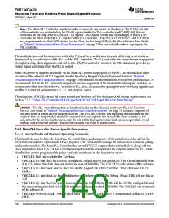
SYSCLK7: 1/6-rate clock for slow peripherals and sources the SYSCLKOUT output pin.
SYSCLK8: 1/z-rate clock. This clock is used as slow_sysclk in the system. Default for this will be 1/64. This is
programmable from /24 to /80.
•
•
•
SYSCLK9: 1/12-rate clock for SmartReflex.
SYSCLK10: 1/3-rate clock for SRIO only.
SYSCLK11: 1/6-rate clock for PSC only.
Only SYSCLK2, SYSCLK5, and SYSCLK8 are programmable on theTMS320C6678 device.
Note—In case any of the other programmable SYSCLKs are set slower than 1/64 rate, then SYSCLK8
(SLOW_SYSCLK) needs to be programmed to either match, or be slower than, the slowest SYSCLK in the
system.
7.5.1.2 Main PLL Controller Operating Modes
The Main PLL Controller has two modes of operation: bypass mode and PLL mode. The mode of operation is
determined by BYPASS bit of the PLL Secondary control register (SECCTL). In PLL mode, SYSCLK1 is generated
from the PLL output using the values set in PLLM and PLLD bit fields in the MAINPLLCTL0 register. In bypass
mode, PLL input is fed directly out as SYSCLK1.
All hosts must hold off accesses to the DSP while the frequency of its internal clocks is changing. A mechanism must
be in place such that the DSP notifies the host when the PLL configuration has completed.
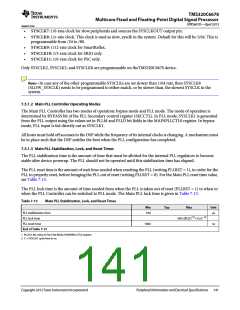
7.5.1.3 Main PLL Stabilization, Lock, and Reset Times
The PLL stabilization time is the amount of time that must be allotted for the internal PLL regulators to become
stable after device powerup. The PLL should not be operated until this stabilization time has elapsed.
The PLL reset time is the amount of wait time needed when resetting the PLL (writing PLLRST = 1), in order for the
PLL to properly reset, before bringing the PLL out of reset (writing PLLRST = 0). For the Main PLL reset time value,
see Table 7-13.
The PLL lock time is the amount of time needed from when the PLL is taken out of reset (PLLRST = 1) to when to
when the PLL Controller can be switched to PLL mode. The Main PLL lock time is given in Table 7-13.
Table 7-13
Main PLL Stabilization, Lock, and Reset Times
Min
Typ
Max
Unit
PLL stabilization time
PLL lock time
100
μs
(2)
500×(PLLD (1)+1)×C
PLL reset time
1000
ns
End of Table 7-13
1 PLLD is the value in PLLD bit fields of MAINPLLCTL0 register
2 C = SYSCLK1 cycle time in ns.
Copyright 2013 Texas Instruments Incorporated
Peripheral Information and Electrical Specifications 141

 TI [ TEXAS INSTRUMENTS ]