TMS320C6672
Multicore Fixed and Floating-Point Digital Signal Processor
SPRS708C—February 2012
www.ti.com
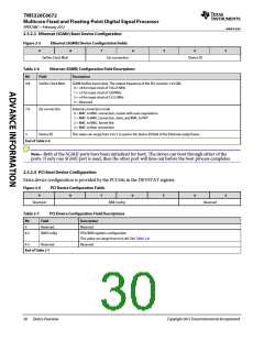
2.5.2.3 Ethernet (SGMII) Boot Device Configuration
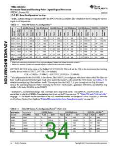
Figure 2-5
9
Ethernet (SGMII) Device Configuration Fields
8
7
6
5
4
3
SerDes Clock Mult
Ext connection
Device ID
Table 2-6
Ethernet (SGMII) Configuration Field Descriptions
Bit
Field Description
9-8
SerDes Clock Mult
Ext connection
Device ID
SGMII SerDes input clock. The output frequency of the PLL must be 1.25 GBs.
0 = ×8 for input clock of 156.25 MHz
1 = ×5 for input clock of 250 MHz
2 = ×4 for input clock of 312.5 MHz
3 = Reserved
7-6
External connection mode
0 = MAC to MAC connection, master with auto negotiation
1 = MAC to MAC connection, slave, and MAC to PHY
2 = MAC to MAC, forced link
3 = MAC to fiber connection
5
End of Table 2-6
This value can range from 0 to 7 is used in the device ID field of the Ethernet-ready frame.
Note—Both of the SGMII ports have been initialized for boot. The device can boot through either of the
ports. If only one SGMII port is used, then the other port will time out before the boot process completes.
2.5.2.4 PCI Boot Device Configuration
Extra device configuration is provided by the PCI bits in the DEVSTAT register.
Figure 2-6
9
PCI Device Configuration Fields
8
7
6
5
4
3
Reserved
BAR Config
Reserved
Table 2-7
PCI Device Configuration Field Descriptions
Field Description
Bit
9
Reserved
Reserved
8-5
BAR Config
PCIe BAR registers configuration
This value can range from 0 to 0xf. See Table 2-8.
Reserved
4-3
Reserved
End of Table 2-7
30
Device Overview
Copyright 2012 Texas Instruments Incorporated

 TI [ TEXAS INSTRUMENTS ]