TMS320C6672
Multicore Fixed and Floating-Point Digital Signal Processor
SPRS708C—February 2012
www.ti.com
2.5 Boot Modes Supported and PLL Settings
The device supports several boot processes, which leverage the internal boot ROM. Most boot processes are software
driven, using the BOOTMODE[3:0] device configuration inputs to determine the software configuration that must
be completed. From a hardware perspective, there are two possible boot modes:
•
Public ROM Boot - C66x CorePac0 is released from reset and begins executing from the L3 ROM base
address. After performing the boot process (e.g., from I2C ROM, Ethernet, or RapidIO), C66x CorePac0 then
begins execution from the provided boot entry point, other C66x CorePac’s are released from reset and begin
executing an IDLE from the L3 ROM. They are then released from IDLE based on interrupts generated by
C66x CorePac0. See the Bootloader for the C66x DSP User Guide in ‘‘Related Documentation from Texas
Instruments’’ on page 69 for more details.
•
Secure ROM Boot - On secure devices, the C66x CorePac0 is released from reset and begin executing from
secure ROM. Software in the secure ROM will free up internal RAM pages, after which C66x CorePac0
initiates the boot process. The C66x CorePac0 performs any authentication and decryption required on the
bootloaded image prior to beginning execution.
The boot process performed by the C66x CorePac0 in public ROM boot and secure ROM boot are determined by
the BOOTMODE[12:0] value in the DEVSTAT register. The C66x CorePac0 reads this value, and then executes the
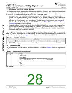
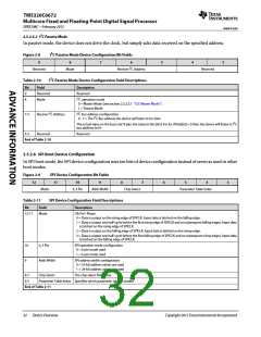
associated boot process in software. Figure 2-2 shows the bits associated with BOOTMODE[12:0].
Figure 2-2
Boot Mode Pin Decoding
Boot Mode Pins
6
12
11
10
9
8
7
5
4
3
2
1
0
PLL Mult I2C /SPI Ext Dev Cfg
Device Configuration
Boot Device
2.5.1 Boot Device Field
The Boot Device field BOOTMODE[2:0] defines the boot device that is chosen. Table 2-3 shows the supported boot
modes.
Table 2-3
Boot Mode Pins: Boot Device Values
Description
Bit
Field
Boot Device
2-0
Device boot mode
0 = EMIF16 / No Boot
1 = Serial Rapid I/O
2 = Ethernet (SGMII) (PASS PLL configuration assumes input rate same as CORECLK(P|N))
3 = Ethernet (SGMII) (PASS PLL configuration assumes input rate same as PASSCLK(P|N))
4 = PCIe
5 = I2C
6 = SPI
7 = HyperLink
End of Table 2-3
28
Device Overview
Copyright 2012 Texas Instruments Incorporated

 TI [ TEXAS INSTRUMENTS ]