TMS320C6672
Multicore Fixed and Floating-Point Digital Signal Processor
SPRS708C—February 2012
www.ti.com
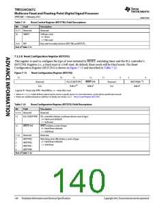
Table 7-21
Reset Control Register (RSTCTRL) Field Descriptions
Bit
Field
Description
31-17 Reserved
Reserved.
16
SWRST
Software reset
0 = Reset
1 = Not reset
15-0
KEY
Key used to enable writes to RSTCTRL and RSTCFG.
End of Table 7-21
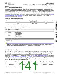
7.5.2.8 Reset Configuration Register (RSTCFG)
This register is used to configure the type of reset initiated by RESET, watchdog timer and the PLL controller’s
RSTCTRL Register; i.e., a Hard reset or a Soft reset. By default, these resets will be Hard resets. The Reset
Configuration Register (RSTCFG) is shown in Figure 7-15 and described in Table 7-22.
Figure 7-15
Reset Configuration Register (RSTCFG)
31
14
13
12
11
4
3
0
(1)
Reserved
R-0
PLLCTLRSTTYPE
R/W-0 (2)
RESETTYPE
R/W-02
Reserved
R-0
WDTYPE[N
R/W-02
]
Legend: R = Read only; R/W = Read/Write; -n = value after reset
1 Where N = 1, 2, 3,....N (Not all these output may be used on a specific device. For more information, see the device-specific data manual)
2 Writes are conditional based on valid key. For details, see Section 7.5.2.7 ‘‘Reset Control Register (RSTCTRL)’’.
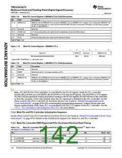
Table 7-22
Reset Configuration Register (RSTCFG) Field Descriptions
Bit
Field
Description
31-14 Reserved
Reserved.
13
PLLCTLRSTTYPE PLL controller initiates a software-driven reset of type:
0 = Hard reset (default)
1 = Soft reset
12
RESETTYPE
RESET initiates a reset of type:
0 = Hard Reset (default)
1 = Soft Reset
11-4
Reserved
WDTYPE3
WDTYPE2
WDTYPE1
WDTYPE0
Reserved.
3
2
1
0
Watchdog timer [N] initiates a reset of type:
0 = Hard Reset (default)
1 = Soft Reset
End of Table 7-22
140
Peripheral Information and Electrical Specifications
Copyright 2012 Texas Instruments Incorporated

 TI [ TEXAS INSTRUMENTS ]