TMP435
SBOS495A –MARCH 2010–REVISED APRIL 2010
www.ti.com
High-Speed Mode
minus the hysteresis value stored in the THERM
Hysteresis Register. The allowable values of
hysteresis are shown in Table 11. The default
hysteresis is 10°C. When the ALERT/THERM2 pin is
configured as a second thermal alarm (Configuration
Register: bit 7 = x, bit 5 = 1), it functions the same as
THERM, but uses the temperatures stored in the
Local/Remote Temperature High Limit Registers to
set its comparison range.
In order for the two-wire bus to operate at frequencies
above 400kHz, the master device must issue a
High-speed
mode
(Hs-mode)
master
code
(00001XXX) as the first byte after a START condition
to switch the bus to high-speed operation. The
TMP435 does not acknowledge this byte, but
switches the input filters on SDA and SCL and the
output filter on SDA to operate in Hs-mode, allowing
transfers at up to 3.4MHz. After the Hs-mode master
code has been issued, the master transmits a
two-wire slave address to initiate a data transfer
operation. The bus continues to operate in Hs-mode
until a STOP condition occurs on the bus. Upon
receiving the STOP condition, the TMP435 switches
the input and output filter back to fast-mode
operation.
When ALERT/THERM2 is configured as ALERT
(Configuration Register: bit 7 = 0, bit 5 = 0), the pin
asserts low when either the measured local or remote
temperature violates the range limit set by the
corresponding Local/Remote Temperature High/Low
Limit Registers. This alert function can be configured
to assert only if the range is violated a specified
number of consecutive times (1, 2, 3, or 4). The
consecutive violation limit is set in the Consecutive
Alert Register. False alerts that occur as a result of
environmental noise can be prevented by requiring
consecutive faults. ALERT also asserts low if the
remote temperature sensor is open-circuit. When the
MASK function is enabled (Configuration Register 1:
bit 7 = 1), ALERT is disabled (that is, masked).
ALERT resets when the master reads the device
address, as long as the condition that caused the
alert no longer persists, and the Status Register has
been reset.
Timeout Function
The serial interface of the TMP435 resets if either
SCL or SDA are held low for 32ms (typical) between
a START and STOP condition. If the TMP435 is
holding the bus low, it releases the bus and waits for
a START condition.
THERM and ALERT/THERM2
The TMP435 has two pins dedicated to alarm
functions, the THERM and ALERT/THERM2 pins.
Both pins are open-drain outputs that each require a
pull-up resistor to V+. These pins can be wire-ORed
together with other alarm pins for system monitoring
of multiple sensors. The THERM pin provides a
thermal interrupt that cannot be software disabled.
The ALERT pin is intended for use as an earlier
warning interrupt, and can be software disabled, or
masked. The ALERT/THERM2 pin can also be
configured for use as THERM2, a second THERM pin
(Configuration Register: AL/TH bit = 1). The default
setting configures pin 6 for the TMP435 to function as
ALERT (AL/TH = 0).
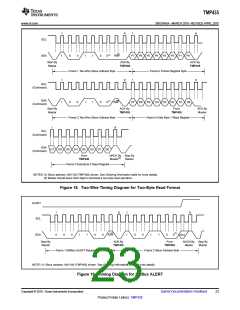
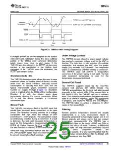
SMBus Alert Function
The TMP435 supports the SMBus Alert function.
When pin 6 is configured as an alert output, the
ALERT pin of the TMP435 may be connected as an
SMBus Alert signal. When a master detects an alert
condition on the ALERT line, the master sends an
SMBus Alert command (00011001) on the bus. If the
ALERT pin of the TMP435 is active, the devices
acknowledge the SMBus Alert command and respond
by returning its slave address on the SDA line. The
eighth bit (LSB) of the slave address byte indicates
whether the temperature exceeding one of the
temperature high limit settings or falling below one of
the temperature low limit settings caused the alert
condition. This bit is high if the temperature is greater
than or equal to one of the temperature high limit
settings; this bit is low if the temperature is less than
one of the temperature low limit settings. See
Figure 20 for details of this sequence.
The THERM pin asserts low when either the
measured local or remote temperature is outside of
the temperature range programmed in the
corresponding Local/Remote THERM Limit Register.
The THERM temperature limit range can be
programmed with a wider range than that of the limit
registers, which allows ALERT to provide an earlier
warning than THERM. The THERM alarm resets
automatically when the measured temperature
returns to within the THERM temperature limit range
24
Submit Documentation Feedback
Copyright © 2010, Texas Instruments Incorporated
Product Folder Link(s): TMP435

 TI [ TEXAS INSTRUMENTS ]