TMP435
www.ti.com
SBOS495A –MARCH 2010–REVISED APRIL 2010
Layout Considerations
temperature offset readings as a result of leakage
paths between DXP or DXN and GND, or
between DXP or DXN and V+.
Remote temperature sensing on the TMP435
measures very small voltages using very low
currents; therefore, noise at the IC inputs must be
minimized. Most applications using the TMP435 have
high digital content, with several clocks and logic
level transitions creating a noisy environment. Layout
should adhere to the following guidelines:
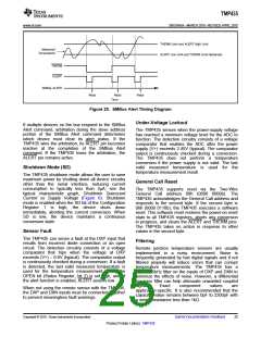
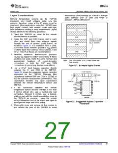
V+
1. Place the TMP435 as close to the remote
junction sensor as possible.
DXP
Ground or V+ layer
on bottom and/or
top, if possible.
DXN
2. Route the DXP and DXN traces next to each
other and shield them from adjacent signals
through the use of ground guard traces, as
shown in Figure 21. If a multilayer PCB is used,
bury these traces between ground or VDD planes
to shield them from extrinsic noise sources. 5 mil
(0,127 mm) PCB traces are recommended.
GND
3. Minimize additional thermocouple junctions
caused by copper-to-solder connections. If these
junctions are used, make the same number and
Note: Use 5mil (.005in, or 0,127mm) traces with
5mil spacing.
approximate
locations
of
copper-to-solder
connections in both the DXP and DXN
connections to cancel any thermocouple effects.
Figure 21. Example Signal Traces
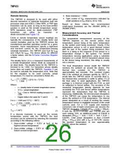
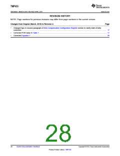
4. Use a 0.1mF local bypass capacitor directly
between the V+ and GND of the TMP435.
Figure 22 shows the suggested bypass capacitor
placement for the TMP435. Minimize filter
capacitance between DXP and DXN to 2200pF or
less for optimum measurement performance. This
capacitance includes any cable capacitance
between the remote temperature sensor and
TMP435.
0.1mF Capacitor
V+
GND
PCB Via
PCB Via
1
2
3
4
5
10
9
DXP
DXN
A0
8
5. If the connection between the remote
temperature sensor and the TMP435 is less than
8 inches (20,32 cm), use a twisted-wire pair
connection. Beyond 8 inches, use a twisted,
shielded pair with the shield grounded as close to
the TMP435 as possible. Leave the remote
sensor connection end of the shield wire open to
avoid ground loops and 60Hz pickup.
7
A1
6
TMP435
Figure 22. Suggested Bypass Capacitor
Placement
6. Thoroughly clean and remove all flux residue in
and around the pins of the TMP435 to avoid
Copyright © 2010, Texas Instruments Incorporated
Submit Documentation Feedback
27
Product Folder Link(s): TMP435

 TI [ TEXAS INSTRUMENTS ]