TMP435
www.ti.com
SBOS495A –MARCH 2010–REVISED APRIL 2010
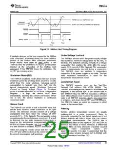
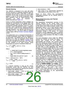
THERM Limit and ALERT High Limit
Measured
Temperature
ALERT Low Limit and THERM Limit Hysteresis
THERM
ALERT
SMBus ALERT
Read
Read
Time
Read
Figure 20. SMBus Alert Timing Diagram
space
Under-Voltage Lockout
If multiple devices on the bus respond to the SMBus
Alert command, arbitration during the slave address
portion of the SMBus Alert command determines
which device must clear its alert status. If the
TMP435 wins the arbitration, its ALERT pin becomes
inactive at the completion of the SMBus Alert
command. If the TMP435 loses the arbitration, the
ALERT pin remains active.
The TMP435 senses when the power-supply voltage
has reached a minimum voltage level for the ADC to
function. The detection circuitry consists of a voltage
comparator that enables the ADC after the power
supply (V+) exceeds 2.45V (typical). The comparator
output is continuously checked during a conversion.
The TMP435 does not perform
a temperature
conversion if the power supply is not valid. The last
valid measured temperature is used for the
temperature measurement result.
Shutdown Mode (SD)
The TMP435 shutdown mode allows the user to save
maximum power by shutting down all device circuitry
other than the serial interface, reducing current
consumption to typically less than 3µA; see the
typical characteristic graph, Shutdown Quiescent
Current vs Supply Voltage (Figure 6). Shutdown
mode is enabled when the SD bit of the Configuration
General Call Reset
The TMP435 supports reset via the Two-Wire
General Call address 00h (0000 0000b). The
TMP435 acknowledges the General Call address and
responds to the second byte. If the second byte is
06h (0000 0110b), the TMP435 executes a software
reset. This software reset restores the power-on reset
state to all TMP435 registers, aborts any conversion
in progress, and clears the ALERT and THERM pins.
The TMP435 takes no action in response to other
values in the second byte.
Register
1
is high; the device shuts down
immediately, aborting the current conversion. When
SD is low, the device maintains
conversion state.
a continuous
Sensor Fault
The TMP435 can sense a fault at the DXP input that
results from incorrect diode connection or an open
circuit. The detection circuitry consists of a voltage
comparator that trips when the voltage at DXP
exceeds (V+) – 0.6V (typical). The comparator output
is continuously checked during a conversion. If a fault
is detected, the last valid measured temperature is
used for the temperature measurement result, the
OPEN bit (Status Register, bit 2) is set high, and, if
the alert function is enabled, ALERT asserts low.
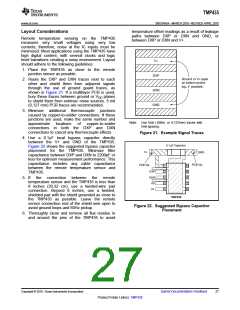
Filtering
Remote junction temperature sensors are usually
implemented in
a noisy environment. Noise is
frequently generated by fast digital signals and if not
filtered properly will induce errors that can corrupt
temperature measurements. The TMP435 has a
built-in 65kHz filter on the inputs of DXP and DXN to
minimize the effects of noise. However, a differential
low-pass filter can help attenuate unwanted coupled
signals.
Exact
component
values
are
When not using the remote sensor with the TMP435,
the DXP and DXN inputs must be connected together
to prevent meaningless fault warnings.
application-specific. It is also recommended that the
capacitor value remains between 0pF to 2200pF with
a series resistance less than 1kΩ.
Copyright © 2010, Texas Instruments Incorporated
Submit Documentation Feedback
25
Product Folder Link(s): TMP435

 TI [ TEXAS INSTRUMENTS ]