TMP112
SBOS473B–MARCH 2009–REVISED JUNE 2009 ......................................................................................................................................................... www.ti.com
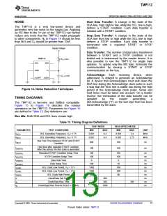
POLARITY (POL)
CONVERTER RESOLUTION (R1/R0)
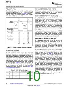
The Polarity bit allows the user to adjust the polarity
of the ALERT pin output. If POL = 0, the ALERT pin
becomes active low, as shown in Figure 13. For POL
= 1, the ALERT pin becomes active high, and the
state of the ALERT pin is inverted.
R1/R0 are read-only bits. The TMP112 converter
resolution is set on start up to '11'. This sets the
temperature register to a 12 bit-resolution.
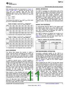
ONE-SHOT/CONVERSION READY (OS)
The TMP112 features a One-Shot Temperature
Measurement mode. When the device is in Shutdown
mode, writing a '1' to the OS bit starts a single
temperature conversion. During the conversion, the
OS bit reads '0'. The device returns to the shutdown
state at the completion of the single conversion. After
the conversion, the OS bit reads '1'. This feature is
useful for reducing power consumption in the
TMP112 when continuous temperature monitoring is
not required.
THIGH
Measured
Temperature
TLOW
TMP112 ALERT PIN
(Comparator Mode)
POL = 0
As a result of the short conversion time, the TMP112
can achieve a higher conversion rate. A single
conversion typically takes 26ms and a read can take
place in less than 20µs. When using One-Shot mode,
30 or more conversions per second are possible.
TMP112 ALERT PIN
(Interrupt Mode)
POL = 0
TMP112 ALERT PIN
(Comparator Mode)
POL = 1
TMP112 ALERT PIN
(Interrupt Mode)
POL = 1
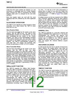
HIGH- AND LOW-LIMIT REGISTERS
In Comparator mode (TM = 0), the ALERT pin
becomes active when the temperature equals or
exceeds the value in THIGH and generates
a
Read
Read
Time
Read
consecutive number of faults according to fault bits
F1 and F0. The ALERT pin remains active until the
temperature falls below the indicated TLOW value for
the same number of faults.
Figure 13. Output Transfer Function Diagrams
In Interrupt mode (TM = 1), the ALERT pin becomes
active when the temperature equals or exceeds the
value in THIGH for a consecutive number of fault
conditions (as shown in Table 9). The ALERT pin
remains active until a read operation of any register
occurs, or the device successfully responds to the
SMBus Alert Response address. The ALERT pin is
also cleared if the device is placed in Shutdown
mode. Once the ALERT pin is cleared, it becomes
FAULT QUEUE (F1/F0)
A
fault condition exists when the measured
temperature exceeds the user-defined limits set in the
THIGH and TLOW registers. Additionally, the number of
fault conditions required to generate an alert may be
programmed using the fault queue. The fault queue is
provided to prevent a false alert as a result of
environmental noise. The fault queue requires
consecutive fault measurements in order to trigger
the alert function. Table 9 defines the number of
measured faults that may be programmed to trigger
an alert condition in the device. For THIGH and TLOW
register format and byte order, see the High- and
Low-Limit Registers section.
active again only when temperature falls below TLOW
,
and remains active until cleared by a read operation
of any register or a successful response to the
SMBus Alert Response address. Once the ALERT
pin is cleared, the above cycle repeats, with the
ALERT pin becoming active when the temperature
equals or exceeds THIGH. The ALERT pin can also be
cleared by resetting the device with the General Call
Reset command. This action also clears the state of
the internal registers in the device, returning the
device to Comparator mode (TM = 0).
Table 9. TMP112 Fault Settings
F1
0
F0
0
CONSECUTIVE FAULTS
1
2
4
6
0
1
1
0
1
1
10
Submit Documentation Feedback
Copyright © 2009, Texas Instruments Incorporated
Product Folder Link(s): TMP112

 TI [ TEXAS INSTRUMENTS ]