TMP112
www.ti.com ......................................................................................................................................................... SBOS473B–MARCH 2009–REVISED JUNE 2009
CONFIGURATION REGISTER
CONVERSION RATE
The Configuration Register is a 16-bit read/write
register used to store bits that control the operational
modes of the temperature sensor. Read/write
operations are performed MSB first. The format and
power-up/reset values of the Configuration Register
are shown in Table 7. For compatibility, the first byte
corresponds to the Configuration Register in the
TMP75 and TMP275. All registers are updated byte
by byte.
The conversion rate bits, CR1 and CR0, configure the
TMP112 for conversion rates of 8Hz, 4Hz, 1Hz, or
0.25Hz. The default rate is 4Hz. The TMP112 has a
typical conversion time of 26ms. To achieve different
conversion rates, the TMP112 makes a conversion
and then powers down and waits for the appropriate
delay set by CR1 and CR0. Table 8 shows the
settings for CR1 and CR0.
Table 8. Conversion Rate Settings
Table 7. Configuration and Power-Up/Reset
Formats
CR1
CR0
CONVERSION RATE
0
0
1
1
0
1
0
1
0.25Hz
1Hz
BYTE
D7
OS
0
D6
R1
1
D5
R0
1
D4
F1
0
D3
F0
0
D2
D1
D0
SD
0
POL TM
4Hz (default)
8Hz
1
0
0
0
0
0
0
CR1 CR0
AL
1
EM
0
0
0
2
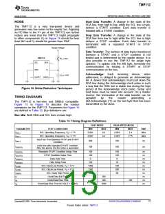
After a power-up or general-call reset, the TMP112
immediately starts conversion, as shown in
1
0
0
0
a
Figure 12. The first result is available after 26ms
(typical). The active quiescent current during
conversion is 40µA (typical at +27°C). The quiescent
current during delay is 2.2µA (typical at +27°C).
EXTENDED MODE (EM)
The Extended mode bit configures the device for
Normal mode operation (EM = 0) or Extended mode
operation (EM
=
1). In Normal mode, the
Temperature Register and high- and low-limit
registers use a 12-bit data format. Normal mode is
used to make the TMP112 compatible with the
TMP75.
Delay(1)
26ms
26ms
Extended mode (EM = 1) allows measurement of
temperatures above +128°C by configuring the
Temperature Register, and high- and low-limit
registers, for 13-bit data format.
Startup
Start of
Conversion
ALERT (AL Bit)
(1) Delay is set by CR1 and CR0.
Figure 12. Conversion Start
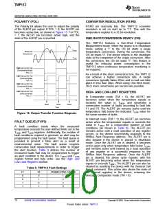
The AL bit is a read-only function. Reading the AL bit
provides information about the comparator mode
status. The state of the POL bit inverts the polarity of
data returned from the AL bit. For POL = 0, the AL bit
reads as '1' until the temperature equals or exceeds
THIGH for the programmed number of consecutive
faults, causing the AL bit to read as '0'. The AL bit
continues to read as '0' until the temperature falls
below TLOW for the programmed number of
consecutive faults, when it again reads as '1'. The
status of the TM bit does not affect the status of the
AL bit.
SHUTDOWN MODE (SD)
The Shutdown mode bit saves maximum power by
shutting down all device circuitry other than the serial
interface, reducing current consumption to typically
less than 0.5µA. Shutdown mode is enabled when
the SD bit = '1'; the device shuts down when current
conversion is completed. When SD = '0', the device
maintains a continuous conversion state.
THERMOSTAT MODE (TM)
The Thermostat mode bit indicates to the device
whether to operate in Comparator mode (TM = 0) or
Interrupt mode (TM = 1). For more information on
Comparator and Interrupt modes, see the High- and
Low-Limit Registers section.
Copyright © 2009, Texas Instruments Incorporated
Submit Documentation Feedback
9
Product Folder Link(s): TMP112

 TI [ TEXAS INSTRUMENTS ]