TLVM13640
SLVSGJ7 – APRIL 2022
www.ti.com
9.2.1.2.2 Output Voltage Setpoint
The output voltage of a TLVM13640 module is externally adjustable using a resistor divider. A recommended
value for RFBB of 10 kΩ establishes a divider current of 0.1 mA. Select the value for RFBT from Table 8-1 or
calculate using Equation 9:
(9)
Choose the closest standard value of 40.2 kΩ for RFBT
.
9.2.1.2.3 Switching Frequency Selection
Connect a 13-kΩ resistor from RT to AGND to set a switching frequency of 1 MHz, which is ideal for an output of
5 V as it establishes an inductor peak-to-peak ripple current in the range of 20% to 40% of the 4-A rated output
current at a nominal input voltage of 24 V.
9.2.1.2.4 Input Capacitor Selection
The TLVM13640 requires a minimum input capacitance of 2 × 10-µF ceramic, preferably with X7R dielectric.
The voltage rating of input capacitors must be greater than the maximum input voltage. For this design, select
two 10-µF, X7R, 50-V, 1210 case size, ceramic capacitors connected from VIN1 and VIN2 to PGND as close as
possible to the module. See Figure 11-2 for recommneded layout placement.
9.2.1.2.5 Output Capacitor Selection
From Table 8-1, the TLVM13640 requires a minimum of 25 µF of effective output capacitance for proper
operation at an output voltage of 5 V. Use high-quality ceramic type capacitors with sufficient voltage and
temperature rating. If needed, connect additional output capacitance to reduce ripple voltage or for applications
with specific load transient requirements.
For this design example, use two 47-µF, 6.3-V or 10-V, X7R, 1210, ceramic capacitors connected close to the
module from the VOUT1 and VOUT2 pins to PGND. The total effective capacitance at 5 V is approximately
52 µF and 38 µF at 25°C and –40°C, respectively.
9.2.1.2.6 Other Connections
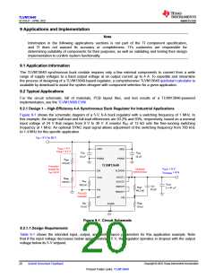
Connect VLDOIN to the 5-V output for best efficiency. To increase phase margin when using an output
capacitance close to the minimum recommended in Table 8-1, use a feedforward capacitor, designated as
CFF in Figure 9-1, across the upper feedback resistor. Based on the feedback resistor values in this application,
a capacitor of 22 pF sets a zero-pole pair at 180 kHz and 900 kHz, respectively.
Copyright © 2022 Texas Instruments Incorporated
22
Submit Document Feedback
Product Folder Links: TLVM13640

 TI [ TEXAS INSTRUMENTS ]