TLK10002
SLLSE75 –MAY 2011
www.ti.com
The MDIO Interface consists of a bi-directional data path (MDIO) and a clock reference (MDC). The port address
is determined by control pins PRTAD[4:0] as described in Table 1.
In Clause 22, the top 4 control pins PRTAD[4:1] determine the device port address. In this mode the 2 individual
channels in TLK10002 are classified as 2 different ports. So for any PRTAD[4:1] value there will be 2 ports per
TLK10002.
TLK10002 will respond if the 4 MSB’s of PHY address field on MDIO protocol (PA[4:1]) matches PRTAD[4:1].
The LSB of PHY address field (PA[0]) will determine which channel/port within TLK10002 to respond to.
If PA[0] = 1'b0, TLK10002 Channel A will respond.
If PA[0] = 1'b1, TLK10002 Channel B will respond.
Write transactions which address an invalid register or device or a read only register will be ignored. Read
transactions which address an invalid register will return a 0.
MDIO Protocol Timing
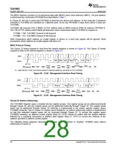
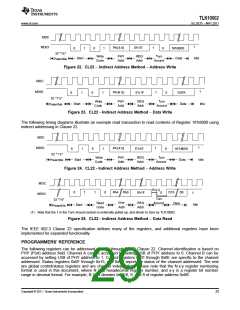
The Clause 22 timing required to read from the internal registers is shown in Figure 20. The Clause 22 timing
required to write to the internal registers is shown in Figure 21.
MDC
Pu(1)
0
1
1
0
PA4 PA0 RA4
RA0
D15
D0
0
1
MDIO
Turn
32 "1's"
Read
Code
PHY
Addr
REG
Addr
Around
Data
Idle
Start
Preamble
(1) Note that the 1 in the Turn Around section is externally pulled up, and driven to Z by TLK10002.
Figure 20. CL22 - Management Interface Read Timing
MDC
1
MDIO
0
1
0
1
PA [4 :0]
RA4 RA 0
1
0
D15
D0
32 "1's"
Write
Code
PHY
Addr
REG
Addr
Turn
Around
Start
Data
Idle
Preamble
Figure 21. CL22 - Management Interface Write Timing
Clause 22 Indirect Addressing
The TLK10002 Register space is divided into two register groups. One register group can be addressed directly
through Clause 22, and one register group can be addressed indirectly through Clause 22. The register group
which can be addressed through Clause 22 indirectly is implemented in the vendor specific register space
(16’h8000 onwards). Due to Clause 22 register space limitations, an indirect addressing method is implemented
so that this extended register space can be accessed through Clause 22. To access this register space
(16’h8000 onwards), an address control register (Reg 30, 5’h1E) should be written with the register address
followed by a read/write transaction to address data register (Reg 31, 5’h1F) to access the contents of the
address specified in address control register.
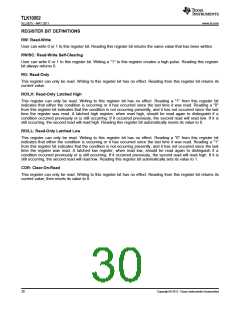
The following timing diagrams illustrate an example write transaction to Register 16’h8000 using indirect
addressing in Clause 22.
28
Copyright © 2011, Texas Instruments Incorporated

 TI [ TEXAS INSTRUMENTS ]