TLC5928
SBVS120A–JULY 2008–REVISED SEPTEMBER 2008 ................................................................................................................................................. www.ti.com
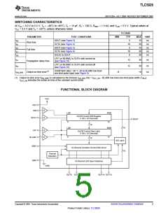
ELECTRICAL CHARACTERISTICS
At VCC = 3.0 V to 5.5 V and TA = –40°C to +85°C. Typical values at VCC = 3.3 V and TA = +25°C, unless otherwise noted.
TLC5928
PARAMETER
TEST CONDITIONS
IOH = –1 mA at SOUT
MIN
TYP
MAX
VCC
0.4
1
UNIT
V
VOH
VOL
IIN
High-level output voltage
Low-level output voltage
Input current
VCC – 0.4
IOL = 1 mA at SOUT
0
V
VIN = VCC or GND at SIN, SCLK, LAT, and BLANK
–1
µA
SIN/SCLK/LAT = low, BLANK = high, VOUTn = 1 V,
RIREF = 27 kΩ
ICC1
ICC2
ICC3
ICC4
IOLC
1
4.5
7
2
8
mA
mA
mA
mA
mA
SIN/SCLK/LAT = low, BLANK = high, VOUTn = 1 V,
RIREF = 3 kΩ
Supply current (VCC
)
SIN/SCLK/LAT/BLANK = low, VOUTn = 1 V,
RIREF = 3 kΩ
18
40
37
SIN/SCLK/LAT/BLANK = low, VOUTn = 1 V,
RIREF = 1.5 kΩ
16
34
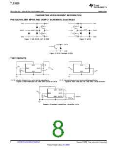
All OUTn = ON, VOUTn = VOUTfix = 1 V, RIREF = 1.5 kΩ
(see Figure 6), at OUT0 to OUT15
Constant output current
Output leakage current
31
All OUTn for constant current driver, all outputs off
BLANK = high, VOUTn = VOUTfix = 17 V, RIREF = 1.5 kΩ
(see Figure 6), at OUT0 to OUT15
IOLKG
0.1
µA
Constant current error
(channel-to-channel)(1)
All OUTn = ON, VOUTn = VOUTfix = 1 V, RIREF = 1.5 kΩ
at OUT0 to OUT15
ΔIOLC
±1
±1
±3
±6
±1
±3
%
%
Constant current error
(device-to-device)(2)
All OUTn = ON, VOUTn = VOUTfix = 1 V, RIREF = 1.5 kΩ
at OUT0 to OUT15
ΔIOLC1
ΔIOLC2
ΔIOLC3
All OUTn = ON, VOUTn = VOUTfix = 1 V, RIREF = 1.5 kΩ
at OUT0 to OUT15
Line regulation(3)
Load regulation(4)
±0.5
±1
%/V
%/V
All OUTn = ON, VOUTn = 1 V to 3V, VOUTfix = 1 V,
RIREF = 1.5 kΩ, at OUT0 to OUT15
T(PTW)
VLOD
Pre-thermal warning threshold
LED open detection threshold
Reference voltage output
Junction temperature(5)
+125
0.25
1.16
+138
0.30
1.20
+150
0.35
1.24
°C
V
All OUTn = ON
VIREF
RIREF = 1.5 kΩ
V
(1) The deviation of each output from the average of OUT0–OUT15 constant current. Deviation is calculated by the formula:
IOUTn
D (%) =
- 1 ´ 100
(IOUT0 + IOUT1 + ... + IOUT14 + IOUT15
)
16
.
(2) The deviation of the OUT0–OUT15 constant current average from the ideal constant current value.
Deviation is calculated by the following formula:
(IOUT0 + IOUT1 + ... IOUT14 + IOUT15
)
- (Ideal Output Current)
16
D (%) =
´ 100
Ideal Output Current
Ideal current is calculated by the formula:
1.20
IOUT(IDEAL) = 42 ´
RIREF
(3) Line regulation is calculated by this equation:
(IOUTn at VCC = 5.5 V) - (IOUTn at VCC = 3.0 V)
D (%/V) =
100
´
(IOUTn at VCC = 3.0 V)
5.5 V - 3 V
(4) Load regulation is calculated by the equation:
(IOUTn at VOUTn = 3 V) - (IOUTn at VOUTn = 1 V)
100
3 V - 1 V
D (%/V) =
´
(IOUTn at VOUTn = 1 V)
(5) Not tested. Specified by design.
4
Submit Documentation Feedback
Copyright © 2008, Texas Instruments Incorporated
Product Folder Link(s): TLC5928

 TI [ TEXAS INSTRUMENTS ]