TLC5928
SBVS120A–JULY 2008–REVISED SEPTEMBER 2008 ................................................................................................................................................. www.ti.com
This integrated circuit can be damaged by ESD. Texas Instruments recommends that all integrated circuits be handled with
appropriate precautions. Failure to observe proper handling and installation procedures can cause damage.
ESD damage can range from subtle performance degradation to complete device failure. Precision integrated circuits may be more
susceptible to damage because very small parametric changes could cause the device not to meet its published specifications.
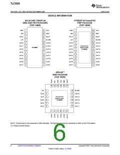
PACKAGE/ORDERING INFORMATION(1)
PRODUCT
PACKAGE-LEAD
ORDERING NUMBER
TLC5928DBQR
TLC5928DBQ
TRANSPORT MEDIA, QUANTITY
Tape and Reel, 2500
Tube, 50
TLC5928
SO-24
TLC5928PWR
TLC5928PW
Tape and Reel, 2000
Tube, 60
TLC5928
TLC5928
TLC5928
TSSOP-24
HTSSOP-24 PowerPAD™
QFN-24(2)
TLC5928PWPR
TLC5928PWP
TLC5928RGER
TLC5928RGE
Tape and Reel, 2000
Tube, 60
Tape and Reel, 3000
Tape and Reel, 250
(1) For the most current package and ordering information see the Package Option Addendum at the end of this document, or see the TI
web site at www.ti.com.
(2) Shaded cells indicate product preview device.
ABSOLUTE MAXIMUM RATINGS(1)(2)
Over operating free-air temperature range, unless otherwise noted.
PARAMETER
TLC5928
–0.3 to +6.0
40
UNIT
V
VCC
IOUT
VIN
Supply voltage: VCC
Output current (dc)
Input voltage range
OUT0 to OUT15
mA
V
SIN, SCLK, LAT, BLANK, IREF
SOUT
–0.3 to VCC + 0.3
–0.3 to VCC + 0.3
–0.3 to +18
+150
V
VOUT
Output voltage range
OUT0 to OUT15
V
TJ(MAX)
TSTG
Operating junction temperature
Storage temperature range
°C
°C
kV
V
–55 to +150
2
Human body model (HBM)
ESD rating
Charged device model (CDM)
500
(1) Stresses above these ratings may cause permanent damage. Exposure to absolute maximum conditions for extended periods may
degrade device reliability. These are stress ratings only, and functional operation of the device at these or any other conditions beyond
those specified is not supported.
(2) All voltage values are with respect to network ground terminal.
DISSIPATION RATINGS
OPERATING FACTOR
ABOVE TA = +25°C
TA < +25°C
POWER RATING
TA = +70°C
POWER RATING
TA = +85°C
POWER RATING
PACKAGE
SO-24
14.3 mW/°C
9.6 mW/°C
28.9 mW/°C
24.8 mW/°C
1782 mW
1194 mW
3611 mW
3106 mW
1140 mW
764 mW
927 mW
621 mW
1878 mW
1615 mW
TSSOP-24
HTSSOP-24(1)
QFN-24(2)
2311 mW
1988 mW
(1) With PowerPAD soldered onto copper area on printed circuit board (PCB); 2 oz. copper. For more information, see SLMA002 (available
for download at www.ti.com).
(2) The package thermal impedance is calculated in accordance with JESD51-5.
2
Submit Documentation Feedback
Copyright © 2008, Texas Instruments Incorporated
Product Folder Link(s): TLC5928

 TI [ TEXAS INSTRUMENTS ]