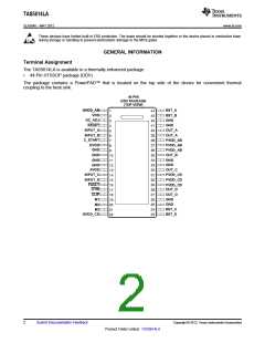
TAS5614LA
SLAS846 –MAY 2012
www.ti.com
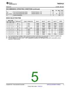
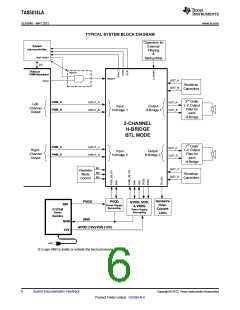
TYPICAL SYSTEM BLOCK DIAGRAM
Capacitors for
System
microcontroller
External
Filtering
&
/AMP RESET
I2C
Startup/Stop
TASxxxx
PWM Modulator
*NOTE1
/RESET
BST_A
BST_B
VALID
Bootstrap
Capacitors
2nd Order
L-C Output
Filter for
each
PWM_A
PWM_B
INPUT_A
INPUT_B
OUT_A
OUT_B
Left-
Input
H-Bridge 1
Output
H-Bridge 1
Channel
Output
H-Bridge
2-CHANNEL
H-BRIDGE
BTL MODE
2nd Order
L-C Output
Filter for
each
PWM_C
PWM_D
INPUT_C
INPUT_D
OUT_C
OUT_D
Right-
Channel
Output
Input
H-Bridge 2
Output
H-Bridge 2
H-Bridge
M1
BST_C
BST_D
Hardwire
Mode
M2
M3
Bootstrap
Capacitors
Control
Hardwire
PVDD
GND
PVDD
Power Supply
Decoupling
GVDD, VDD,
& VREG
Power Supply
36V
Over-
Current
Limit
SYSTEM
Power
Supplies
Decoupling
GND
12V
GVDD (12V)/VDD (12V)
VAC
(1) Logic AND is inside or outside the micro processor.
6
Submit Documentation Feedback
Copyright © 2012, Texas Instruments Incorporated
Product Folder Link(s): TAS5614LA

 TI [ TEXAS INSTRUMENTS ]