RM46L450
RM46L850
SPNS184 –SEPTEMBER 2012
www.ti.com
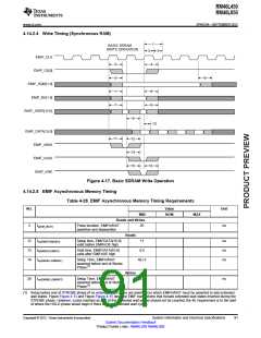
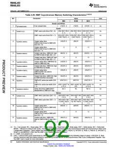
Table 4-29. EMIF Asynchronous Memory Switching Characteristics(1)(2)(3)
NO
Parameter
Value
NOM
Unit
MIN
MAX
Reads and Writes
1
3
td(TURNAROUND)
Turn around time
(TA)*E -3
Reads
(RS+RST+RH)* (RS+RST+RH)* (RS+RST+RH)*
E -3 E + 3
(RS+RST+RH+( (RS+RST+RH+( (RS+RST+RH+(
(TA)*E
(TA)*E + 3
ns
tc(EMRCYCLE)
EMIF read cycle time (EW = 0)
EMIF read cycle time (EW = 1)
ns
ns
E
EWC*16))*E -3
EWC*16))*E
EWC*16))*E +
3
4
5
tsu(EMCEL-EMOEL)
Output setup time,
EMIFnCS[4:2] low to EMIFnOE
low (SS = 0)
(RS)*E-3
(RS)*E
(RS)*E+3
ns
ns
Output setup time,
EMIFnCS[4:2] low to EMIFnOE
low (SS = 1)
-3
0
+3
th(EMOEH-EMCEH)
Output hold time, EMIFnOE high
to EMIFnCS[4:2] high (SS = 0)
(RH)*E -3
-3
(RH)*E
0
(RH)*E + 3
+3
ns
ns
ns
ns
ns
Output hold time, EMIFnOE high
to EMIFnCS[4:2] high (SS = 1)
6
7
8
tsu(EMBAV-EMOEL)
th(EMOEH-EMBAIV)
tsu(EMBAV-EMOEL)
Output setup time, EMIFBA[1:0]
valid to EMIFnOE low
(RS)*E-3
(RH)*E-3
(RS)*E-3
(RS)*E
(RH)*E
(RS)*E
(RS)*E+3
(RH)*E+3
(RS)*E+3
Output hold time, EMIFnOE high
to EMIFBA[1:0] invalid
Output setup time,
EMIFADDR[12:0] valid to
EMIFnOE low
9
th(EMOEH-EMAIV)
tw(EMOEL)
Output hold time, EMIFnOE high
to EMIFADDR[12:0] invalid
(RH)*E-3
(RH)*E
(RH)*E+3
ns
ns
ns
ns
10
EMIFnOE active low width (EW
= 0)
(RST)*E-3
(RST)*E
(RST)*E+3
EMIFnOE active low width (EW
= 1)
(RST+(EWC*16 (RST+(EWC*16 (RST+(EWC*16
)) *E-3
))*E
)) *E+3
11
15
td(EMWAITH-EMOEH)
Delay time from EMIFnWAIT
deasserted to EMIFnOE high
3E-3
4E
4E+3
Writes
(WS+WST+WH (WS+WST+WH (WS+WST+WH
)* E-3 )*E )* E+3
tc(EMWCYCLE)
EMIF write cycle time (EW = 0)
EMIF write cycle time (EW = 1)
ns
ns
(WS+WST+WH (WS+WST+WH (WS+WST+WH
+( EWC*16))*E +(E WC*16))*E +( EWC*16))*E
-3
+ 3
16
17
tsu(EMCEL-EMWEL)
Output setup time,
EMIFnCS[4:2] low to EMIFnWE
low (SS = 0)
(WS)*E -3
(WS)*E
0
(WS)*E + 3
ns
ns
ns
Output setup time,
EMIFnCS[4:2] low to EMIFnWE
low (SS = 1)
-3
+3
th(EMWEH-EMCEH)
Output hold time, EMIFnWE
high to EMIFnCS[4:2] high (SS =
0)
(WH)*E-3
(WH)*E
(WH)*E+3
(1) TA = Turn around, RS = Read setup, RST = Read strobe, RH = Read hold, WS = Write setup, WST = Write strobe, WH = Write hold,
MEWC = Maximum external wait cycles. These parameters are programmed via the Asynchronous Bank and Asynchronous Wait Cycle
Configuration Registers. These support the following ranges of values: TA[4–1], RS[16–1], RST[64–1], RH[8–1], WS[16–1], WST[64–1],
WH[8–1], and MEWC[1–256]. See the EMIF User’s guide for more information.
(2) E = EMIF_CLK period in ns.
(3) EWC = external wait cycles determined by EMIFnWAIT input signal. EWC supports the following range of values. EWC[256–1]. Note
that the maximum wait time before timeout is specified by bit field MEWC in the Asynchronous Wait Cycle Configuration Register. See
the EMIF User’s Guide for more information.
92
System Information and Electrical Specifications
Submit Documentation Feedback
Product Folder Links: RM46L450 RM46L850
Copyright © 2012, Texas Instruments Incorporated

 TI [ TEXAS INSTRUMENTS ]