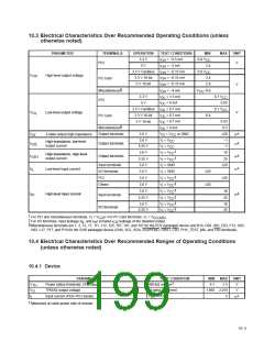
10 Electrical Characteristics
†
10.1 Absolute Maximum Ratings Over Operating Temperature Ranges
Supply voltage range, VR_PORT . . . . . . . . . . . . . . . . . . . . . . . . . . . . . . . . . . . . . . . . . . . . . . . . . . . −0.2 V to 2.2 V
ANALOGV . . . . . . . . . . . . . . . . . . . . . . . . . . . . . . . . . . . . . . . . . . . . . . . . . . −0.3 V to 4 V
CC
V
PLLV
. . . . . . . . . . . . . . . . . . . . . . . . . . . . . . . . . . . . . . . . . . . . . . . . . . . . . . . . . . −0.3 V to 4 V
CC
. . . . . . . . . . . . . . . . . . . . . . . . . . . . . . . . . . . . . . . . . . . . . . . . . . . . . . −0.3 V to 4 V
. . . . . . . . . . . . . . . . . . . . . . . . . . . . . . . . . . . . . . . . . . . . . . . . . . . . . . −0.5 V to 5.5 V
. . . . . . . . . . . . . . . . . . . . . . . . . . . . . . . . . . . . . . . . . . . . . . . . . . . . . . . . −0.5 V to 5.5 V
CC
V
V
CCCB
CCP
Clamping voltage range, V
and V
. . . . . . . . . . . . . . . . . . . . . . . . . . . . . . . . . . . . . . . . . . . . −0.5 V to 6 V
CCP
CCCB
Input voltage range, V : PCI, CardBus, PHY, miscellaneous . . . . . . . . . . . . . . . . . . . . . . . −0.5 V to V
Output voltage range, V : PCI, CardBus, PHY, miscellaneous . . . . . . . . . . . . . . . . . . . . −0.5 V to V
+ 0.5 V
+ 0.5 V
I
CC
CC
O
IK
OK
Input clamp current, I (V < 0 or V > V ) (see Note 1) . . . . . . . . . . . . . . . . . . . . . . . . . . . . . . . . . . . . . 20 mA
I
I
CC
Output clamp current, I
(V < 0 or V > V ) (see Note 2) . . . . . . . . . . . . . . . . . . . . . . . . . . . . . . . . . 20 mA
O O CC
Human Body Model (HBM) ESD performance . . . . . . . . . . . . . . . . . . . . . . . . . . . . . . . . . . . . . . . . . . . . . . 1500 V
Operating free-air temperature, T . . . . . . . . . . . . . . . . . . . . . . . . . . . . . . . . . . . . . . . . . . . . . . . . . . . . . 0°C to 70°C
A
Storage temperature range, T . . . . . . . . . . . . . . . . . . . . . . . . . . . . . . . . . . . . . . . . . . . . . . . . . . . . −65°C to 150°C
stg
Virtual junction temperature, T . . . . . . . . . . . . . . . . . . . . . . . . . . . . . . . . . . . . . . . . . . . . . . . . . . . . . . . . . . . . 150°C
J
†
Stresses beyond those listed under absolute maximum ratings may cause permanent damage to the device. These are stress ratings only and
functional operation of the device at these or any other conditions beyond those indicated under recommended operating conditions is not implied.
Exposure to absolute-maximum-rated conditions for extended periods may affect device reliability.
NOTES: 1. Applies for external input and bidirectional buffers. V > V
does not apply to fail-safe terminals. PCI terminals and miscellaneous
I
CC
terminals are measured with respect to V
limit specified applies for a dc condition.
instead of V . PC Card terminals are measured with respect to CardBus V . The
CC CC
CCP
2. Applies for external output and bidirectional buffers. V > V
does not apply to fail-safe terminals. PCI terminals and miscellaneous
O
CC
terminals are measured with respect to V
limit specified applies for a dc condition.
instead of V . PC Card terminals are measured with respect to CardBus V . The
CC CC
CCP
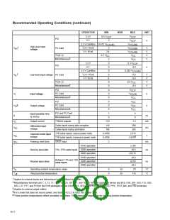
10.2 Recommended Operating Conditions (see Note 3)
OPERATION
MIN
1.6
NOM
1.8
MAX
UNIT
VR_PORT
ANALOGV
1.8 V
3.3 V
3.3 V
2
V
V
V
V
(see Table 2−4 for description)
3
3
3.3
3.6
3.6
CC
V
CC
3.3
PLLV
3.3 V
3.3 V
5 V
3
3
3.3
3.3
5
3.6
3.6
CC
V
V
V
PCI and miscellaneous I/O clamp voltage
PC Card I/O clamp voltage
CCP
4.75
3
5.25
3.6
3.3 V
5 V
3.3
5
V
CCCB
4.75
5.25
NOTE 3: Unused terminals (input or I/O) must be held high or low to prevent them from floating.
10−1

 TI [ TEXAS INSTRUMENTS ]