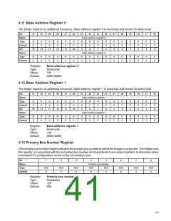
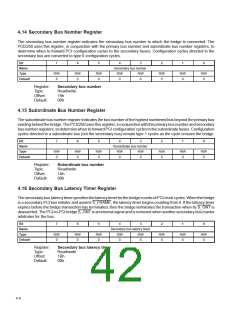
4.14 Secondary Bus Number Register
The secondary bus number register indicates the secondary bus number to which the bridge is connected. The
PCI2250 uses this register, in conjunction with the primary bus number and subordinate bus number registers, to
determine when to forward PCI configuration cycles to the secondary buses. Configuration cycles directed to the
secondary bus are converted to type 0 configuration cycles.
Bit
7
6
5
4
3
2
1
0
Name
Type
Default
Secondary bus number
R/W
0
R/W
0
R/W
0
R/W
0
R/W
0
R/W
0
R/W
0
R/W
0
Register:
Type:
Offset:
Default:
Secondary bus number
Read/write
19h
00h
4.15 Subordinate Bus Number Register
The subordinate bus number register indicates the bus number of the highest numbered bus beyond the primary bus
existingbehindthebridge. ThePCI2250usesthisregister, inconjunctionwiththeprimarybusnumberandsecondary
bus number registers, to determine when to forward PCI configuration cycles to the subordinate buses. Configuration
cycles directed to a subordinate bus (not the secondary bus) remain type 1 cycles as the cycle crosses the bridge.
Bit
7
6
5
4
3
2
1
0
Name
Type
Default
Subordinate bus number
R/W
0
R/W
0
R/W
0
R/W
0
R/W
0
R/W
0
R/W
0
R/W
0
Register:
Type:
Offset:
Default:
Subordinate bus number
Read/write
1Ah
00h
4.16 Secondary Bus Latency Timer Register
ThesecondarybuslatencytimerspecifiesthelatencytimerforthebridgeinunitsofPCIclockcycles. Whenthebridge
is a secondary PCI bus initiator and asserts S_FRAME, the latency timer begins counting from 0. If the latency timer
expires before the bridge transaction has terminated, then the bridge terminates the transaction when its S_GNT is
deasserted. The PCI-to-PCI bridge S_GNT is an internal signal and is removed when another secondary bus master
arbitrates for the bus.
Bit
7
6
5
4
3
2
1
0
Name
Type
Default
Secondary bus latency timer
R/W
0
R/W
0
R/W
0
R/W
0
R/W
0
R/W
0
R/W
0
R/W
0
Register:
Type:
Offset:
Default:
Secondary bus latency timer
Read/write
1Bh
00h
4–8

 TI [ TEXAS INSTRUMENTS ]