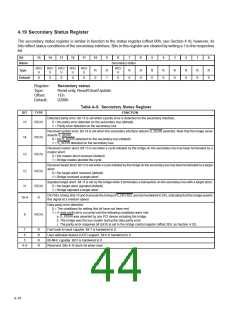
4.19 Secondary Status Register
The secondary status register is similar in function to the status register (offset 06h, see Section 4.4); however, its
bits reflect status conditions of the secondary interface. Bits in this register are cleared by writing a 1 to the respective
bit.
Bit
15
14
13
12
11
10
9
8
7
6
5
4
3
2
1
0
Name
Secondary status
R/C/
U
R/C/
U
R/C/
U
R/C/
U
R/C/
U
R/C/
R
Type
R
0
R
1
R
0
R
0
R
0
R
0
R
0
R
0
R
0
U
Default
0
0
0
0
0
0
0
Register:
Type:
Secondary status
Read-only, Read/Clear/Update
Offset:
Default:
1Eh
0200h
Table 4–5. Secondary Status Register
BIT
TYPE
FUNCTION
Detected parity error. Bit 15 is set when a parity error is detected on the secondary interface.
0 = No parity error detected on the secondary bus (default)
15
R/C/U
1 = Parity error detected on the secondary bus
Received system error. Bit 14 is set when the secondary interface detects S_SERR asserted. Note that the bridge never
asserts S_SERR.
14
13
12
R/C/U
0 = No S_SERR detected on the secondary bus (default)
1 = S_SERR detected on the secondary bus
Received master abort. Bit 13 is set when a cycle initiated by the bridge on the secondary bus has been terminated by a
master abort.
R/C/U
R/C/U
0 = No master abort received (default)
1 = Bridge master aborted the cycle
Receivedtargetabort. Bit12issetwhenacycleinitiatedbythebridgeonthesecondarybushasbeenterminatedbyatarget
abort.
0 = No target abort received (default)
1 = Bridge received a target abort
Signaled target abort. Bit 11 is set by the bridge when it terminates a transaction on the secondary bus with a target abort.
0 = No target abort signaled (default)
11
R/C/U
R
1 = Bridge signaled a target abort
DEVSEL timing. Bits 10 and 9 encode the timing of S_DEVSEL and are hardwired to 01b, indicating that the bridge asserts
this signal at a medium speed.
10–9
Data parity error detected.
0 = The conditions for setting this bit have not been met
1 = A data parity error occurred and the following conditions were met:
a. S_PERR was asserted by any PCI device including the bridge.
b. The bridge was the bus master during the data parity error.
c. The parity error response bit (bit 0) is set in the bridge control register (offset 3Eh, se Section 4.32).
8
R/C/U
7
6
R
R
R
R
Fast back-to-back capable. Bit 7 is hardwired to 0.
User-definable feature (UDF) support. Bit 6 is hardwired to 0.
66-MHz capable. Bit 5 is hardwired to 0.
5
4–0
Reserved. Bits 4–0 return 0s when read.
4–10

 TI [ TEXAS INSTRUMENTS ]