ONET1131EC
ZHCSFG0 –SEPTEMBER 2016
www.ti.com.cn
Feature Description (continued)
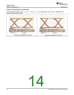
7.3.5 DC Offset Cancellation and Cross Point Control
The ONET1131EC transmitter has DC offset cancellation to compensate for internal offset voltages. The offset
cancellation can be disabled by setting TXOC_DIS = 1 (bit 2 of register 10).
The crossing point can be moved toward the one level by setting TXCPSGN = 1 (bit 7 of register 14) and it can
be moved toward the zero level by setting TXCPSGN = 0. The percentage of shift depends upon the register
settings of the transmitter cross-point adjustment bits TXCPADJ[0..6] (register 14).
7.3.6 Bias Current Generation and APC Loop
The bias current for the laser is turned off by default and has to be enabled by setting the laser bias current
enable bit TXBIASEN = 1 (bit 2 of register 1). In open loop operation, selected by setting TXOLENA = 1 (bit 4 of
register 1), the bias current is set directly by the 10-bit wide control word TXBIAS[0..9] (register 15 and register
16). In Automatic Power Control (APC) mode, selected by setting TXOLENA = 0, the bias current depends on
the register settings TXBIAS[0..9] and the coupling ratio (CR) between the laser bias current and the photodiode
current. CR = IBIAS/IPD. If the photodiode cathode is connected to VCC and the anode is connected to the PD pin
(PD pin is sinking current) set TXPDPOL = 1 (bit 0 of register 1). If the photodiode anode is connected to ground
and the cathode is connected to the PD pin (PD pin is sourcing current), set TXPDPOL = 0.
Three photodiode current ranges can be selected by means of the photodiode current range bits TXPDRNG[0..1]
(bits 5 and 6 of register 1). The photodiode range should be chosen to keep the laser bias control DAC,
TXBIAS[0..9], close to the center of its range. This keeps the laser bias current set point resolution high. For
details regarding the bias current setting in open-loop mode as well as in closed-loop mode, see the Register
Mapping table.
The ONET1131EC has the ability to source or sink the bias current. The default condition is for the BIAS pin to
source the current (TXBIASPOL = 0). To act as a sink, set TXBIASPOL = 1 (bit 1 of register 1).
The bias current is monitored using a current mirror with a gain equal to 1/100. By connecting a resistor between
MONB and GND, the bias current can be monitored as a voltage across the resistor. A low temperature
coefficient precision resistor should be used. The bias current can also be monitored as a 10 bit unsigned digital
word by setting the transmitter bias current digital monitor selection bit TXDMONB = 1 (bit 5 of register 16) and
removing the resistor from MONB to ground.
The photodiode current is monitored using a current mirror with various gains that are dependent upon the
photodiode current range being used. By connecting a resistor between MONP and GND, the photodiode current
can be monitored as a voltage across the resistor. A low temperature coefficient precision resistor should be
used. The photodiode current can also be monitored as a 10 bit unsigned digital word by setting the transmitter
photodiode current digital monitor selection bit TXDMONP = 1 (bit 6 of register 16) and removing the resistor
from MONP to ground.
7.3.7 Laser Safety Features and Fault Recovery Procedure
The ONET1131EC provides built in laser safety features. The following fault conditions are detected if the
transmitter fault detection enable bit TXFLTEN = 1 (bit 3 of register 1):
1. Voltage at MONB exceeds the bandgap voltage (1.2 V) or, alternately, if TXDMONB = 1 and the bias current
exceeds the bias current monitor fault threshold set by TXBMF[0..7] (register 17). When using the digital
monitor, the resistor from the MONB pin to ground must be removed.
2. Voltage at MONP exceeds the bandgap voltage (1.2 V) and the analog photodiode current monitor fault
trigger bit, TXMONPFLT (bit 7 of register 1), is set to 1. Alternately, a fault can be triggered if TXDMONP = 1
and the photodiode current exceeds the photodiode current monitor fault threshold set by TXPMF[0..7]
(register 18). When using the digital monitor, the resistor from the MONP pin to ground must be removed.
3. Photodiode current exceeds 150% of its set value,
4. Bias control DAC drops in value by more than 50% in one step.
If the fault detection is being used then to avoid a fault from occurring at start-up it is recommended to set up the
required bias current and APC loop conditions first and enable the laser bias current (TXBIASEN = 1) as the last
step in the sequence of commands.
18
Copyright © 2016, Texas Instruments Incorporated

 TI [ TEXAS INSTRUMENTS ]