ONET1131EC
www.ti.com.cn
ZHCSFG0 –SEPTEMBER 2016
Feature Description (continued)
The output driver is set to differential output by default. In order to reduce the power consumption for single-
ended applications driving an electroabsorptive modulated laser (EML) the output drive register 13 should be set
to single-ended mode. The single-ended output signal is enabled by setting the transmitter mode select bit
TXMODE = 1 (bit 6 of register 13). The positive output is active by default. To enable the negative output and
disable the positive output set TXOUTSEL = 1 (bit 7 of register 13).
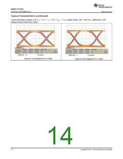
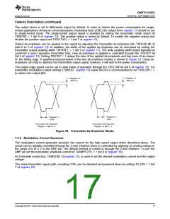
Output de-emphasis can be applied to the signal by adjusting the transmitter de-emphasis bits TXDEADJ[0..3]
(bits 0 to 3 of register 13). In addition, the width of the applied de-emphasis can be increased by setting the
transmitter output peaking width TXPKSEL = 1 (bit 6 of register 11). The wide peaking width would typically be
useful for a more capacitive transmitter load. How de-emphasis is applied is controlled through the TXSTEP bit
(bit 5 of register 13). Setting TXSTEP = 1 delays the time of the applied de-emphasis and has more of an impact
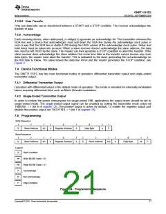
on the falling edge. A graphical representation of the two de-emphasis modes is shown in Figure 23. Using de-
emphasis can help to optimize the transmitted output signal; however, it will add to the power consumption.
The output edge speed can be set to slow mode of operation through the TXSLOW bit (bit 4 of register 13). For
transmitter modulation output settings (TXMOD - register 12) below 0xC0 it is recommended to set TXSLOW = 1
to reduce the output jitter.
Register 13
Register 13
Bits 0œ3
Bits 0œ3
Register 11
Bit 6
Register 11
Bit 6
Transmitter De-Emphasis
Register 13 Bit 5 = 0
Transmitter De-Emphasis
Register 13 Bit 5 = 1
Figure 23. Transmitter De-Emphasis Modes
7.3.4 Modulation Current Generator
The modulation current generator provides the current for the high speed output driver described above. The
circuit can be digitally controlled through the 2-wire interface block or controlled by applying an analog voltage in
the range of 0 to 2 V to the AMP pin. The default method of control is through the 2-wire interface. To use the
AMP pin set the transmitter amplitude control bit TXAMPCTRL = 1 (bit 0 of register 10).
An 8-bit wide control bus, TXMOD[0..7] (register 12), is used to set the desired modulation current and the output
voltage.
The entire transmitter signal path, including CDR, can be disabled and powered down by setting TX_DIS = 1 (bit
7 of register 10).
Copyright © 2016, Texas Instruments Incorporated
17

 TI [ TEXAS INSTRUMENTS ]