OMAP-L137 Low-Power Applications Processor
SPRS563A–SEPTEMBER 2008–REVISED OCTOBER 2008
www.ti.com
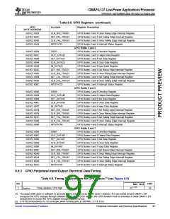
Table 6-9. Timing Requirements for GPIO Inputs (see Figure 6-9) (continued)
NO.
UNIT
MIN MAX
2C(1)(2)
2
tw(GPIL)
Pulse duration, GPIx low
ns
Table 6-10. Switching Characteristics Over Recommended Operating Conditions for GPIO Outputs
(see Figure 6-9)
NO.
PARAMETER
Pulse duration, GPOx high
Pulse duration, GPOx low
UNIT
MIN
2C(1) (2)
2C(1)(2)
MAX
3
4
tw(GPOH)
tw(GPOL)
ns
ns
(1) This parameter value should not be used as a maximum performance specification. Actual performance of back-to-back accesses of the
GPIO is dependent upon internal bus activity.
(2) C=SYSCLK4 period in ns. For example, when running parts at 300 MHz, C=13.33 ns
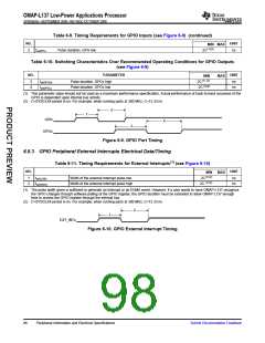
2
1
GPIx
4
3
GPOx
Figure 6-9. GPIO Port Timing
6.8.3 GPIO Peripheral External Interrupts Electrical Data/Timing
Table 6-11. Timing Requirements for External Interrupts(1) (see Figure 6-10)
NO.
UNIT
MIN
MAX
1
2
tw(ILOW)
tw(IHIGH)
Width of the external interrupt pulse low
Width of the external interrupt pulse high
2C(1)(2)
ns
ns
(1)(2)
2C
(1) The pulse width given is sufficient to generate an interrupt or an EDMA event. However, if a user wants to have OMAP-L137 recognize
the GPIO changes through software polling of the GPIO register, the GPIO duration must be extended to allow OMAP-L137 enough
time to access the GPIO register through the internal bus.
(2) C=SYSCLK4 period in ns. For example, when running parts at 300 MHz, C=13.33 ns
2
1
EXT_INTx
Figure 6-10. GPIO External Interrupt Timing
98
Peripheral Information and Electrical Specifications
Submit Documentation Feedback

 TI [ TEXAS INSTRUMENTS ]