OMAP-L137 Low-Power Applications Processor
SPRS563A–SEPTEMBER 2008–REVISED OCTOBER 2008
www.ti.com
6.7.1 ARM CPU Interrupts
The ARM9 CPU core supports 2 direct interrupts: FIQ and IRQ. The ARM Interrupt Controller on the
OMAP-L13x extends the number of interrupts to 100, and provides features like programmable masking,
priority, hardware nesting support, and interrupt vector generation. The OMAP-L13x ARM Interrupt
controller is enhanced from previous devices like the DM6446 and DM355.
6.7.1.1 ARM Interrupt Controller (AINTC) Interrupt Signal Hierarchy
On OMAP-L13x, the ARM Interrupt controller organizes interrupts into the following hierarchy:
•
Peripheral Interrupt Requests
Individual Interrupt Sources from Peripherals
100 System Interrupts
–
•
–
One or more Peripheral Interrupt Requests are combined (fixed configuration) to generate a
System Interrupt.
–
After prioritization, the AINTC will provide an interrupt vector based unique to each System Interrupt
•
32 Interrupt Channels
–
–
Each System Interrupt is mapped to one of the 32 Interrupt Channels
Channel Number determines the first level of prioritization, Channel 0 is highest priority and 31
lowest.
–
If more than one system interrupt is mapped to a channel, priority within the channel is determined
by system interrupt number (0 highest priority)
•
•
Host Interrupts (FIQ and IRQ)
–
–
Interrupt Channels 0 and 1 generate the ARM FIQ interrupt
Interrupt Channels 2 through 31 Generate the ARM IRQ interrupt
Debug Interrupts
–
–
Two Debug Interrupts are supported and can be used to trigger events in the debug subsystem
Sources can be selected from any of the System Interrupts or Host Interrupts
6.7.1.2 AINTC Hardware Vector Generation
The AINTC also generates an interrupt vector in hardware for both IRQ and FIQ host interrupts. This may
be used to accelerate interrupt dispatch. A unique vector is generated for each of the 100 system
interrupts. The vector is computed in hardware as:
VECTOR = BASE + (SYSTEM INTERRUPT NUMBER × SIZE)
Where BASE and SIZE are programmable. The computed vector is a 32-bit address which may
dispatched to using a single instruction of type LDR PC, [PC, #-<offset_12>] at the FIQ and IRQ vector
locations (0xFFFF0018 and 0xFFFF001C respectively).
6.7.1.3 AINTC Hardware Interrupt Nesting Support
Interrupt nesting occurs when an interrupt service routine re-enables interrupts, to allow the CPU to
interrupt the ISR if a higher priority event occurs. The AINTC provides hardware support to facilitate
interrupt nesting. It supports both global and per host interrupt (FIQ and IRQ in this case) automatic
nesting. If enabled, the AINTC will automatically update an internal nesting register that temporarily masks
interrupts at and below the priority of the current interrupt channel. Then if the ISR re-enables interrupts;
only higher priority channels will be able to interrupt it. The nesting level is restored by the ISR by writing
to the nesting level register on completion. Support for nesting can be enabled/disabled by software, with
the option of automatic nesting on a global or per host interrupt basis; or manual nesting.
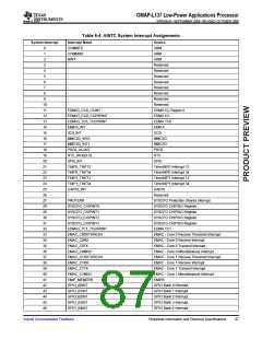
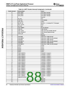
6.7.1.4 AINTC System Interrupt Assignments on OMAP-L137
System Interrupt assignments for the OMAP-L137 are listed in Table 6-4
86
Peripheral Information and Electrical Specifications
Submit Documentation Feedback

 TI [ TEXAS INSTRUMENTS ]