OMAP-L137 Low-Power Applications Processor
www.ti.com
SPRS563A–SEPTEMBER 2008–REVISED OCTOBER 2008
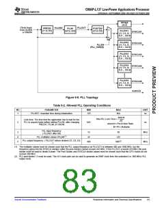
DIV4p5
(/4.5)
Clock Input
from CLKIN
or OSCIN
PLLOUT
PLLREF
PREDIV
(/1 to /32)
PLLM
(x4 to x32)
POSTDIV
1
(/2 to /32)
PLLDIV1
(/1, 1.5, /2,
/2.5 ... /32.5)
SYSCLK1
SYSCLK2
SYSCLK3
SYSCLK4
0
PLLDIV2
(/1, 1.5, /2,
/2.5 ... /32.5)
PLLEN
(PLL_CSR[0])
PLLDIV3
(/1, 1.5, /2,
/2.5 ... /32.5)
PLLDIV4
(/1, 1.5, /2,
/2.5 ... /32.5)
PLLDIV9
(/1, 1.5, /2,
/2.5 ... /32.5)
SYSCLK9
AUXCLK
Figure 6-8. PLL Topology
Table 6-2. Allowed PLL Operating Conditions
NO
PARAMETER
MIN
MAX
N/A
2000 N
UNIT
1
PLLRST: Assertion time during initialization
125
ns
Max PLL Lock Time =
Lock time: The time that the application has to wait for the
PLL to acquire locks before setting PLLEN, after changing
PREDIV, PLLM, or OSCIN
m
2
N/A
ns
where N = Pre-Divider Ratio
M = PLL Multiplier
PLL input frequency
( PLLREF after D0)
PLL multiplier values (PLLM)(1)
3
4
5
12
x4
50
x32
MHz
MHz
PLL output frequency. ( PLLOUT before dividers D1, D2, D3,
....)
400
600(2)
(1) The multiplier values must be chosen such that the PLL output frequency (at PLLOUT) is between 400 and 1000 MHz, but the
frequency going into the SYSCLK dividers (after the post divider) cannot exceed 410 MHz. If the PLLOUT exceeds 410 MHz the post
divider must be used to divide it down. The Post Divider and SYSCLK divider values must be chosen such that the CPU clocks do not
exceed 300 MHz.
(2) PLL post divider / 2 must be used. The /4.5 clock path can be used to generate an EMIF clock from the undivided (i.e. 600 MHz) PLL
output clock.
Submit Documentation Feedback
Peripheral Information and Electrical Specifications
83

 TI [ TEXAS INSTRUMENTS ]