MSP430F530x, MSP430F5310
www.ti.com
SLAS677B –SEPTEMBER 2010–REVISED MARCH 2011
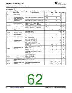
REF, Built-In Reference
over recommended ranges of supply voltage and operating free-air temperature (unless otherwise noted)
(1)
PARAMETER
TEST CONDITIONS
VCC
MIN
TYP
MAX UNIT
REFVSEL = {2} for 2.5 V
REFON = 1
3 V
2.51 ±1.5%
1.99 ±1.5%
1.5 ±1.5%
Positive built-in reference
voltage
REFVSEL = {1} for 2.0 V
REFON = 1
VREF+
3 V
V
V
REFVSEL = {0} for 1.5 V
REFON = 1
2.2 V/ 3 V
REFVSEL = {0} for 1.5 V
REFVSEL = {1} for 2.0 V
REFVSEL = {2} for 2.5 V
2.2
2.2
2.7
AVCC minimum voltage,
Positive built-in reference
active
AVCC(min)
fADC10CLK = 5.0 MHz
REFON = 1, REFBURST = 0,
REFVSEL = {2} for 2.5 V
3 V
3 V
3 V
18
24
21
µA
µA
µA
fADC10CLK = 5.0 MHz
REFON = 1, REFBURST = 0,
REFVSEL = {1} for 2.0 V
Operating supply current
into AVCC terminal
IREF+
15.5
(2)
fADC10CLK = 5.0 MHz
REFON = 1, REFBURST = 0,
REFVSEL = {0} for 1.5V
13.5
30
21
50
Temperature coefficient of
built-in reference
IVREF+ = 0 A
REFVSEL = (0, 1, 2}, REFON = 1
ppm/
°C
TCREF+
ISENSOR
(3)
2.2 V
3 V
20
20
22
22
Operating supply current
REFON = 0, INCH = 0Ah,
ADC10ON = N A, TA = 30°C
µA
mV
V
(4)
into AVCC terminal
2.2 V
3 V
770
770
1.1
1.5
ADC10ON = 1, INCH = 0Ah,
TA = 30°C
(5)
VSENSOR
See
2.2 V
3 V
1.06
1.46
1.14
1.54
ADC10ON = 1, INCH = 0Bh,
VMID is ~0.5 × VAVCC
VMID
tSENSOR(sample)
tVMID(sample)
AVCC divider at channel 11
Sample time required if
ADC10ON = 1, INCH = 0Ah,
Error of conversion result ≤ 1 LSB
30
1
µs
µs
(6)
channel 10 is selected
Sample time required if
channel 11 is selected
ADC10ON = 1, INCH = 0Bh,
Error of conversion result ≤ 1 LSB
(7)
AVCC = AVCC (min) - AVCC(max)
TA = 25 °C
REFVSEL = (0, 1, 2}, REFON = 1
Power supply rejection ratio
(dc)
PSRR_DC
120
µV/V
AVCC = AVCC (min) - AVCC(max)
Power supply rejection ratio TA = 25 °C
PSRR_AC
tSETTLE
6.4
75
mV/V
(ac)
f = 1 kHz, ΔVpp = 100 mV
REFVSEL = (0, 1, 2}, REFON = 1
Settling time of reference
voltage
AVCC = AVCC (min) - AVCC(max)
REFVSEL = (0, 1, 2}, REFON = 0 → 1
µs
(8)
(1) The leakage current is defined in the leakage current table with P6.x/Ax parameter.
(2) The internal reference current is supplied via terminal AVCC. Consumption is independent of the ADC10ON control bit, unless a
conversion is active. The REFON bit enables to settle the built-in reference before starting an A/D conversion.
(3) Calculated using the box method: (MAX(-40 to 85°C) – MIN(-40 to 85°C)) / MIN(-40 to 85°C)/(85°C – (–40°C)).
(4) The sensor current ISENSOR is consumed if (ADC10ON = 1 and REFON = 1) or (ADC10ON = 1 and INCH = 0Ah and sample signal is
high). When REFON = 1, ISENSOR is already included in IREF+
.
(5) The temperature sensor offset can be as much as ±20°C. A single-point calibration is recommended in order to minimize the offset error
of the built-in temperature sensor.
(6) The typical equivalent impedance of the sensor is 51 kΩ. The sample time required includes the sensor-on time tSENSOR(on)
(7) The on-time tVMID(on) is included in the sampling time tVMID(sample); no additional on time is needed.
(8) The condition is that the error in a conversion started after tREFON is less than ±0.5 LSB.
.
Copyright © 2010–2011, Texas Instruments Incorporated
Submit Documentation Feedback
61

 TI [ TEXAS INSTRUMENTS ]