LM3410, LM3410Q
SNVS541G –OCTOBER 2007–REVISED MAY 2013
www.ti.com
PINTERNAL = PCOND + PSW = 107 mW
(48)
Calculating RθJA and RΨJC
T - TA
T - TCase
J
J
:
RYJC =
RqJA
=
PDissipation
PDissipation
(49)
We now know the internal power dissipation, and we are trying to keep the junction temperature at or below
125°C. The next step is to calculate the value for RθJA and/or RΨJC. This is actually very simple to accomplish,
and necessary if you think you may be marginal with regards to thermals or determining what package option is
correct.
The LM3410 has a thermal shutdown comparator. When the silicon reaches a temperature of 165°C, the device
shuts down until the temperature drops to 150°C. Knowing this, one can calculate the RθJA or the RΨJC of a
specific application. Because the junction to top case thermal impedance is much lower than the thermal
impedance of junction to ambient air, the error in calculating RΨJC is lower than for RθJA . However, you will need
to attach a small thermocouple onto the top case of the LM3410 to obtain the RΨJC value.
Knowing the temperature of the silicon when the device shuts down allows us to know three of the four variables.
Once we calculate the thermal impedance, we then can work backwards with the junction temperature set to
125°C to see what maximum ambient air temperature keeps the silicon below the 125°C temperature.
Procedure:
Place your application into a thermal chamber. You will need to dissipate enough power in the device so you can
obtain a good thermal impedance value.
Raise the ambient air temperature until the device goes into thermal shutdown. Record the temperatures of the
ambient air and/or the top case temperature of the LM3410. Calculate the thermal impedances.
Example from previous calculations (SOT-23 Package):
PINTERNAL = 107 mW
(50)
(51)
(52)
TA @ Shutdown = 155°C
TC @ Shutdown = 159°C
T - TA
T - TCase-Top
J
J
:
RYJC =
RqJA
=
PDissipation
PDissipation
(53)
(54)
(55)
R
θJA SOT-23 = 93°C/W
ΨJC SOT-23 = 56°C/W
R
Typical WSON and MSOP-PowerPad typical applications will produce RθJA numbers in the range of 50°C/W to
65°C/W, and RΨJC will vary between 18°C/W and 28°C/W. These values are for PCB’s with two and four layer
boards with 0.5 oz copper, and four to six thermal vias to bottom side ground plane under the DAP. The thermal
impedances calculated above are higher due to the small amount of power being dissipated within the device.
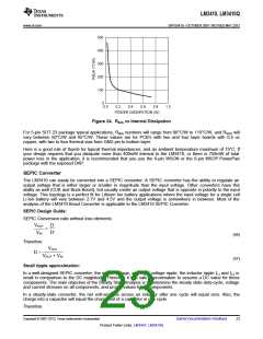
Note: To use these procedures it is important to dissipate an amount of power within the device that will indicate
a true thermal impedance value. If one uses a very small internal dissipated value, one can see that the thermal
impedance calculated is abnormally high, and subject to error. Figure 24 shows the nonlinear relationship of
internal power dissipation vs . RθJA
.
22
Submit Documentation Feedback
Copyright © 2007–2013, Texas Instruments Incorporated
Product Folder Links: LM3410 LM3410Q

 TI [ TEXAS INSTRUMENTS ]