LM3410, LM3410Q
SNVS541G –OCTOBER 2007–REVISED MAY 2013
www.ti.com
Calculating Efficiency and Junction Temperature
We will talk more about calculating proper junction temperature with relative certainty in a moment. For now we
need to describe how to calculate the junction temperature and clarify some common misconceptions.
TJ - TA
RqJA
=
PDissipation
(14)
A common error when calculating RθJA is to assume that the package is the only variable to consider.
RθJA [variables]:
•
•
Input Voltage, Output Voltage, Output Current, RDS(ON)
Ambient temperature and air flow
•
•
Internal and External components power dissipation
Package thermal limitations
•
PCB variables (copper weight, thermal via’s, layers component placement)
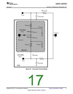
Another common error when calculating junction temperature is to assume that the top case temperature is the
proper temperature when calculating RθJC. RθJC represents the thermal impedance of all six sides of a package,
not just the top side. This document will refer to a thermal impedance called RΨJC. RΨJC represents a thermal
impedance associated with just the top case temperature. This will allow one to calculate the junction
temperature with a thermal sensor connected to the top case.
The complete LM3410 Boost converter efficiency can be calculated in the following manner.
POUT
h =
PIN
or
POUT
h =
POUT + PLOSS
(15)
Power loss (PLOSS) is the sum of two types of losses in the converter, switching and conduction. Conduction
losses usually dominate at higher output loads, where as switching losses remain relatively fixed and dominate at
lower output loads.
Losses in the LM3410 Device:
PLOSS = PCOND + PSW + PQ
Where
•
PQ = quiescent operating power loss
(16)
Conversion ratio of the Boost Converter with conduction loss elements inserted:
≈
∆
’
÷
Å
≈
’
÷
÷
◊
VOUT
D x VD
1
∆
∆
÷
÷
1
Å
D
∆
1-
=
∆
V
RDCR + D x R
V
(
)
IN
DSON
IN
«
∆
∆
«
÷
÷
◊
1+
Å2
R OUT
D
Where
•
RDCR = Inductor series resistance
(17)
(18)
VOUT
ROUT
=
ILED
One can see that if the loss elements are reduced to zero, the conversion ratio simplifies to:
18
Submit Documentation Feedback
Copyright © 2007–2013, Texas Instruments Incorporated
Product Folder Links: LM3410 LM3410Q

 TI [ TEXAS INSTRUMENTS ]