LM3410, LM3410Q
www.ti.com
SNVS541G –OCTOBER 2007–REVISED MAY 2013
VOUT
VIN
1
=
D‘
(19)
(20)
And we know:
h
VOUT
=
VIN
D‘
Therefore:
Å
≈
∆
D x VD
’
÷
1-
V
VOUT
∆
∆
÷
÷
IN
Å
h =
=
D
V
RDCR + D x R
(
)
IN
DSON
∆
∆
«
÷
÷
◊
1+
Å2
ROUT
D
(21)
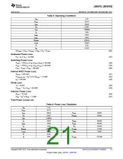
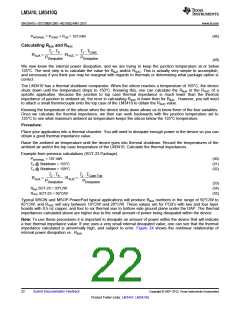
Calculations for determining the most significant power losses are discussed below. Other losses totaling less
than 2% are not discussed.
A simple efficiency calculation that takes into account the conduction losses is shown below:
Å
≈
∆
D x VD
’
÷
1-
V
∆
∆
÷
÷
IN
h ö
RDCR + D x R
(
)
DSON
∆
∆
«
÷
÷
◊
1+
Å2
ROUT
D
(22)
The diode, NMOS switch, and inductor DCR losses are included in this calculation. Setting any loss element to
zero will simplify the equation.
VD is the forward voltage drop across the Schottky diode. It can be obtained from the manufacturer’s Electrical
Characteristics section of the data sheet.
The conduction losses in the diode are calculated as follows:
PDIODE = VD x ILED
(23)
Depending on the duty cycle, this can be the single most significant power loss in the circuit. Care should be
taken to choose a diode that has a low forward voltage drop. Another concern with diode selection is reverse
leakage current. Depending on the ambient temperature and the reverse voltage across the diode, the current
being drawn from the output to the NMOS switch during time D could be significant, this may increase losses
internal to the LM3410 and reduce the overall efficiency of the application. Refer to Schottky diode
manufacturer’s data sheets for reverse leakage specifications, and typical applications within this data sheet for
diode selections.
Another significant external power loss is the conduction loss in the input inductor. The power loss within the
inductor can be simplified to:
2
PIND = IIN RDCR
(24)
Or
2
≈
∆
∆
«
’
÷
÷
◊
IO RDCR
P
=
IND
'
D
(25)
The LM3410 conduction loss is mainly associated with the internal power switch:
PCOND-NFET = I2SW-rms x RDSON x D
(26)
19
Copyright © 2007–2013, Texas Instruments Incorporated
Submit Documentation Feedback
Product Folder Links: LM3410 LM3410Q

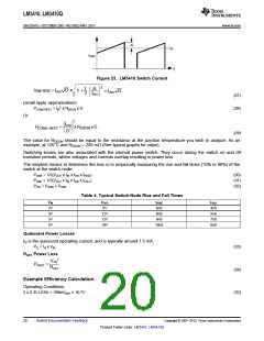
 TI [ TEXAS INSTRUMENTS ]