4.0 Registers (Continued)
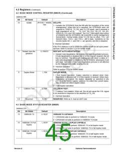
4.2 BASIC MODE CONTROL REGISTER (BMCR)
Address 00h
Bit
Bit Name
Default
Description
15
Reset
0, RW/SC
RESET:
1 = Software Reset
0 = Normal Operation
This bit sets the status and control registers of the PHY to their default
states. Setting this bit will also re-latch in all hardware configuration pin
values. This bit, which is self-clearing, returns a value of one until the
reset process is complete. Software should wait 500µs after device
power on before attempting a software reset. Refer to section 3.10.3 for
further detail.
14
Loopback
0, RW
LOOPBACK:
1 = Loopback Enabled
0 = Normal Operation
The loopback function enables MII transmit data to be routed to the MII
receive data path. When set, this bit enables loopback for either
10BASE-T or 100BASE-X modes of operation.
Setting this bit during 100BASE-TX operation may cause the DP83840A
to enter a 550 µs “dead time” before any valid data transmit or receive
operations can commence.
This bit takes priority over the loopback control bits 8 and 9 in the
LBREMR register (address 18h).
13
12
Speed Selection
1, RW
SPEED SELECT:
1 = 100 Mb/s
0 = 10 Mb/s
Link speed is selected by this bit or by Auto-Negotiation if bit 12 of this
register is set (in which case, the value of this bit is ignored). The latched-
in state of pins AN0 and AN1 will also effect the state of this bit and take
precedence over the Auto-Negotiation Enable bit 12.
Auto-Negotiation
Enable
1, RW
AUTO-NEGOTIATION ENABLE:
1 = Auto-Negotiation Enabled--bits 8 and 13 of this register are ignored
when this bit is set.
0 = Auto-Negotiation Disabled--bits 8 and 13 determine the link speed
and mode.
If the PHY is configured for non-Auto-Negotiation upon power-up/reset
and it is then decided that Auto-Negotiation is to be enabled through
software, this bit must first be cleared and then set in order for it to take
effect. This bit is intended only to control the state of Auto-Negotiation
and should not be regarded as status. Refer to section3.9.2 for further
detail.
11
Reserved
0, RW
RESERVED:
Write as 0, read as don’t care.
Version A
National Semiconductor
43

 TI [ TEXAS INSTRUMENTS ]