3.0 Functional Description (Continued)
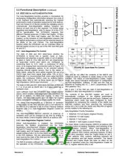
will result in a 550µs down-time where the 100BASE-TX
descrambler must reacquire synchronization with the
scrambled data stream before any valid data will appear at
the receive MII RXD[3:0] outputs.
3.11 LOOPBACK OPERATION
The DP83840A supports several different modes of
loopback operation for diagnostic purposes.
3.11.1 10BASE-T Loopback
3.12 ALTERNATIVE 100BASE-X OPERATION
The loopback option for 10BASE-T operation can be
selected via the serial MII either by asserting the Loopback
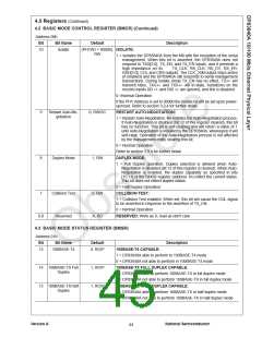
bit (bit 14) in the Basic Mode Control Register (address
00h), or by asserting the 10BT_LPBK bit (bit 11) in the
Loopback, Bypass and Receiver Error Mask Register
(address 18h). Asserting either of these bits will cause the
10BASE-T data present at the transmit MII data inputs to
be routed through the entire 10BASE-T transceiver and
back to the receive MII data outputs. During this loopback
mode, the Manchester encoded 10BASE-T data will not be
present at either the TXU+/- or TXS+/- serial differential
outputs.
The DP83840A 10/100 Physical Layer device supports one
standard and three alternative modes when operating at
100 Mb/s.
3.12.1 Translational (normal) Mode
The first mode is referred to as the “Translational” mode.
This is the standard and most commonly used operating
mode where all transmit and receive functions are enabled
in order to condition the data as it flows through the
Physical Layer between the MAC and cable. All of the
transmit and receive blocks as depicted in Figures 4 and 5
are enabled (not bypassed).
Normal 10BASE-T operation, in order to be standard
compliant, also loops back the MII transmit data to the MII
receive data. However, the data is also allowed to pass
through the 10BASE-T transmitter and out either the
TXU+/- or TXS+/- outputs as well.
3.12.2 Transparent Mode
The second mode is referred to as “Transparent”. In this
mode, the 4B/5B translators in both the transmit and
receive sections are bypassed as might be required in
certain repeater applications. This is accomplished either
by configuring the BP4B5B pin (100) of the DP83840A to a
3.11.2 100BASE-X Loopback
The loopback options for 100BASE-X operation can be logic high level prior to power-up/hardware reset or by
selected by asserting the Loopback bit (bit 14) in the Basic setting the BP_4B5B bit (bit 14) of the LBREMR register
Mode Control Register (address 00h), or by selecting the (address 18h).
desired mode as determined by the LB[1:0] (bits 9 and 8) in
In “Transparent” mode, all remaining functional blocks
the Loopback, Bypass and Receiver Error Mask Register
within the 100BASE-X transmit and receive sections are
(address 18h).
still operational. This allows the 5B serial code-group on
Asserting the Loopback bit (bit 14) in the Basic Mode the twisted pair to be presented as descrambled data,
Control Register (address 00h) will cause the same without conversion to 4B, to the MII. Since the MII normally
loopback of MII transmit to MII receive as described only carries a nibble wide word, the fifth bit, which is the
previously in the 10BASE-T loopback section, except at 25 new MSB, is carried on the RX_ER and TX_ER signals for
MHz due to 100BASE-X operation.
receive and transmit operations respectively.
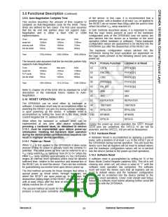
The LB[1:0] bits (bits 9 and 8) of the LBREMR (address In the “Transparent” mode, all of the clock to data timing for
18h) allow for three different modes of operation:
1. bit 9 = 0, bit 8 = 0; Normal operation without loopback
2. bit 9 = 0, bit 8 = 1; PMD loopback operation
3. bit 9 = 1, bit 8 = 0; Remote Loopback
both MII transmit and MII receive operations remains the
same as in “Translational” mode. However, upon reception
of a packet, the /J/K/ start of stream delimiter is not
replaced by the /5/5/ MAC preamble nor is the /T/R/ end of
stream delimiter removed from the packet before
presentation to the MII receive RXD[3:0] and RX_ER
outputs. Similarly, the transmit MII data TXD[3:0] and
TX_ER must already have /J/K/ and /T/R/ packet delimiters
in place. Therefore, the repeater controller device is
responsible for receiving the packet delimiters intact as well
as transmitting these delimiters intact back to the
DP83840A device(s).
The first mode allows normal operation without any form of
loopback.
The second mode asserts the LBEN output of the
DP83840A which, when connected to the LBEN input of
the twisted pair transceiver (DP83223A), forces the twisted
pair transceiver into loopback mode. Therefore, when the
DP83840A is transmitting 100BASE-X serial data from its
serial TD+/- outputs to the twisted pair transceiver, this
data is immediately routed back to the RD+/- 100BASE-X
serial inputs of the DP83840A device.
The receive data valid flag, RX_DV, operates the same
during “Transparent” mode as it does in “Translational”
mode. Additionally, Idles are passed to and from the MII as
/00000/.
The third mode selects the Remote Loopback operation. In
this mode, the DP83840A device serves as a “remote
loopback” for the far end partner. Serial data received off
the twisted pair cable is routed, via the DP83223A, into the
RD+/- serial inputs of the DP83840A where it is then routed
back to the TD+/- serial outputs of the DP83840A and
finally launched back onto the twisted pair cable, via the
DP83223A, and sent back to the far-end partner.
Finally, the “Transparent” mode of operation will operate
the same when the DP83840A is in either node mode or
repeater mode with the only difference being CRS
functionality. As in “translational” mode, if the DP83840A is
configured for repeater operation, the CRS signal will be
suppressed during transmit such that only actual network
collisions will be flagged.
In each of the 100BASE-X loopback modes, except for
Remote Loopback, the assertion of the loopback function
Version A
National Semiconductor
40

 TI [ TEXAS INSTRUMENTS ]