4.0 Registers (Continued)
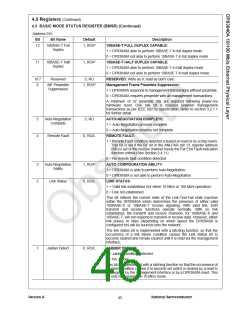
4.3 BASIC MODE STATUS REGISTER (BMSR) (Continued)
Address 01h
Bit
Bit Name
Default
Description
12
10BASE-T Full
Duplex
1, RO/P
10BASE-T FULL DUPLEX CAPABLE:
1 = DP83840A able to perform 10BASE-T in full duplex mode
0 = DP83840A not able to perform 10BASE-T in full duplex mode
10BASE-T HALF DUPLEX CAPABLE:
11
10BASE-T Half
Duplex
1, RO/P
1 = DP83840A able to perform 10BASE-T in half duplex mode
0 = DP83840A not able to perform 10BASE-T in half duplex mode
RESERVED: Write as 0, read as don't care.
10:7
6
Reserved
0, RO
MF Preamble
Suppression
1, RO/P
Management Frame Preamble Suppression:
1 = DP83840A responds to management transactions without preamble.
0 = DP83840A requires preamble with all management transactions.
A minimum of 32 preamble bits are required following power-on/
hardware reset. One Idle bit is required between management
transactions as per IEEE 802.3u specification. Refer to section 3.2.1.1
for further detail.
5
4
Auto-Negotiation
Complete
0, RO
AUTO-NEGOTIATION COMPLETE:
1 = Auto-Negotiation process complete
0 = Auto-Negotiation process not complete
REMOTE FAULT:
Remote Fault
0, RO/L
1 = Remote Fault condition detected (cleared on read or by a chip reset).
This bit is set if the RF bit in the ANLPAR (bit 13, register address
05h) is set or the receive channel meets the Far End Fault Indication
function criteria (See Section 3.4.11).
0 = No remote fault condition detected
AUTO CONFIGURATION ABILITY:
3
2
Auto-Negotiation
Ability
1, RO/P
0, RO/L
1 = DP83840A is able to perform Auto-Negotiation
0 = DP83840A is not able to perform Auto-Negotiation
LINK STATUS:
Link Status
1 = Valid link established (for either 10 Mb/s or 100 Mb/s operation)
0 = Link not established
This bit reflects the current state of the Link-Test-Fail state machine
within the DP83840A which determines the presence of either valid
100BASE-X or 10BASE-T receive signaling. With valid link, both
transmit and receive functions operate normally. With no link
established, the transmit and receive channels, for 100BASE-X and
10BASE-T, will not respond to transmit or receive data. However, either
link pulses or Idles (depending on which speed the DP83840A is
configured for) will be sourced onto the network.
The link status bit is implemented with a latching function, so that the
occurrence of a link failure condition causes the Link Status bit to
become cleared and remain cleared until it is read via the management
interface.
1
Jabber Detect
0, RO/L
JABBER DETECT:
1 = Jabber condition detected
0 = No Jabber
This bit is implemented with a latching function so that the occurrence of
a jabber condition causes it to become set until it is cleared by a read to
this register by the management interface or by a DP83840A reset. This
bit only has meaning in 10 Mb/s mode.
Version A
National Semiconductor
45

 TI [ TEXAS INSTRUMENTS ]